Ford Mustang (1999-2004) Service Manual: Installation
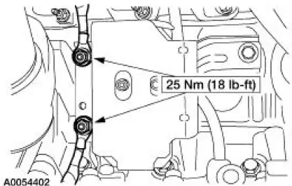
LH mount
1. Position the engine mount and install the bolt and studbolts.
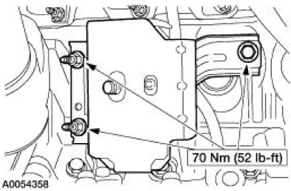
2. Attach the ground cables and install the nuts.
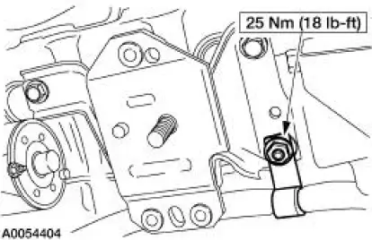
RH mount
3. Position the engine mount and install the bolts and studbolt.
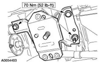
4. Attach the wiring harness and install the nut.
Both mounts
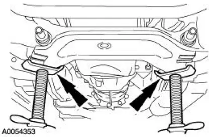
5. Using the jackstands, raise the subframe into position.
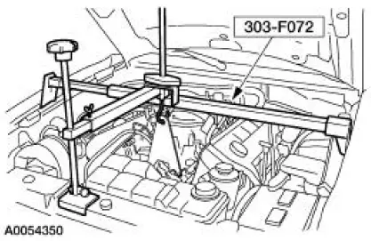
6. NOTE: RH shown, LH similar.
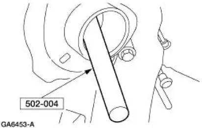
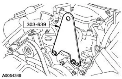
Using the special tool, align the subframe.
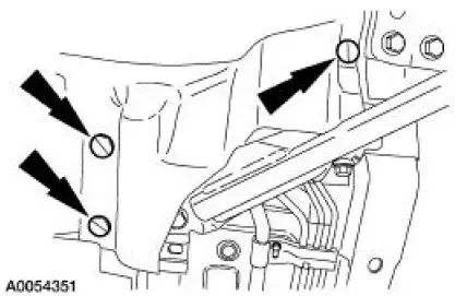
7. NOTE: RH shown, LH similar.
Install the four bolts.
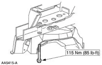
8. NOTE: RH shown, LH similar.
Install the four bolts.
9. Remove the jackstands.
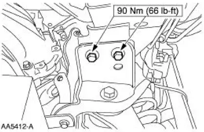
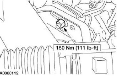
10. NOTE: RH shown, LH similar.
Install the two engine mount nuts.
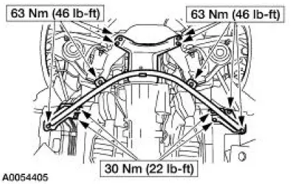
11. Position the cross-brace support and install the 13 bolts.
12. NOTE: RH shown, LH similar Install the six splash-shield pushpins.
13. Install the front springs. For additional information, refer to Section.
14. Remove the special tool.
15. Remove the special tool.
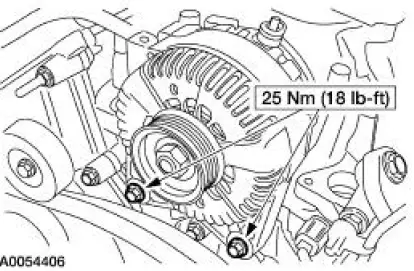
16. Position the generator and install the bolts.
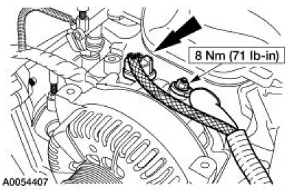
17. Connect the generator electrical connections.
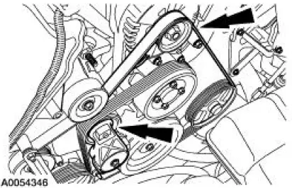
18. Rotate the drive belt tensioner clockwise and attach the drive belt to the generator pulley.
- Make sure the drive belt is routed correctly and is aligned correctly installed on each pulley.
19. Connect the battery ground cable. For additional information, refer to Section.
20. Install the coolant bypass tube. For additional information, refer to Section.
 Removal
Both mounts
1. Disconnect the battery ground cable. For additional information, refer to
Section.
2. Remove the coolant bypass tube. For additional information, refer to Section.
3. Rotate the driv ...
 Engine (Removal)
Special Tool(s)
Lifting Bracket, Engine
303-D087 (D93P-6001-A1)
Lifting Bracket, Engine
303-D088 (D93P-6001-A2)
Spreader Bar
303-D089 (D93P-6001-A3)
Rem ...
Other materials:
Transmission Fluid Drain and Refill
Special Tool(s)
Automatic Transmission Flush
and Fill Machine
211-00018
Automatic Transmission Flush
and Fill Machine
199-00010 or equivalent
Material
Item
Specification
MERCON V Automatic
Transmission Fluid
XT-5-QM
M ...
Component Tests
Starter Motor -Voltage Drop Test
WARNING: When servicing starter motor or carrying out other underhood
work in the
vicinity of the starter motor, be aware that the heavy gauge battery input lead
at the starter
solenoid is "electrically hot" at all times. A p ...
Booster seats
WARNING: Never place, or allow a child to place, the shoulder
belt under a child’s arm or behind the back because it reduces
the protection for the upper part of the body and may increase the risk
of injury or death in a crash.
Use a belt-positioning booster ...
