Ford Mustang (1999-2004) Service Manual: Pinpoint Test N: DTC B1869 - Air Bag Indicator Inoperative
Normal Operation
The air bag indicator is designed to illuminate for 6 (+/-2) seconds when the ignition switch is turned to the RUN position. This initial 6 seconds of illumination is considered normal operation and is called proveout of the air bag indicator. The air bag indicator is then used to warn the driver that there is a fault in the air bag supplemental restraint system (SRS).
The restraints control module (RCM) monitors the air bag indicator for open and short to ground conditions. If the RCM detects an open or short to ground condition on the air bag indicator circuit, it will store a diagnostic trouble code (DTC) B1869 in memory.
If the RCM detects an air bag indicator failure in addition to another SRS failure, the RCM will send a signal to the generic electronic module (GEM) to produce five sets of five tone bursts.
Possible Causes
An air bag indicator inoperative condition can be caused by:
- a damaged wiring on circuit 608 (BK/YE).
- a damaged or burned out air bag indicator.
- worn or damaged instrument cluster.
- an RCM internal concern.
PINPOINT TEST N: DTC B1869 - AIR BAG INDICATOR INOPERATIVE
| Test Step | Result / Action to Take |
| N1 CHECK FOR A HARD OR INTERMITTENT DTC | Yes This is a hard fault. The fault condition is still present. This fault cannot be cleared until it is corrected and the DTC is no longer retrieved during the on-demand self test. GO to N2 . No This is an intermittent fault. The fault conditions not present at this time. GO to N5 . |
|
|
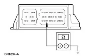
| N2 CHECK THE RCM | Yes INSTALL a new RCM. GO to N6 . No GO to N3 . |
| WARNING: If the supplemental restraint system
(SRS) is
being serviced, the system must be deactivated and restraint
system diagnostic tools must be installed. Refer to Air Bag
Supplemental Restraint System (SRS) in this section.
The air bag restraint system diagnostic tools must be removed and the air bag modules reconnected when the system is reactivated to avoid non-deployment in a collision, resulting in possible personal injury. NOTE: Diagnostics or repairs are not to be performed on a seat equipped with a seat side air bag with the seat in the vehicle. Prior to attempting to diagnose or repair a seat concern when equipped with a seat side air bag, the seat must be removed from the vehicle and the restraint system diagnostic tools must be installed in the seat side air bag electrical connectors. The restraint system diagnostic tools must be removed prior to operating the vehicle over the road. NOTE: After diagnosing or repairing an SRS, the restraint system diagnostic tools must be removed before operating the vehicle over the road. NOTE: After diagnosing or repairing a seat system, the restraint system diagnostic tools must be removed before operating the vehicle over the road. NOTE: The SRS must be fully operational and free of faults before releasing the vehicle to the customer.
|
|
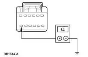
| N3 CHECK CIRCUIT 608 (BK/YE) FOR A SHORT TO GROUND | Yes REPAIR the circuit. GO to N6 . No GO to N4 . |
|
|
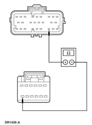
| N4 CHECK CIRCUIT 608 (BK/YE) FOR AN OPEN | Yes REPAIR the circuit. GO to N6 . No REPAIR the instrument cluster. GO to N6 . |
|
|
| N5 CHECK FOR AN INTERMITTENT FAULT | Yes CHECK for causes of intermittent short to ground or open on circuit 608 (BK/YE). Attempt to recreate the hard fault by flexing the wire harness and cycling the ignition key frequently. REPAIR any intermittent concerns found. GO to N6 . No GO to N6 . |
|
|
| N6 CHECK FOR ADDITIONAL DTCs | Yes Do not clear any DTCs until all DTCs have been resolved. GO to the Restraints Control Module (RCM) Diagnostic Trouble Code (DTC) Priority Table in this section for pinpoint test direction. No RECONNECT the system. REACTIVATE the system. PROVE OUT the system. REFER to Air Bag Supplemental Restraint System (SRS) in this section. CLEAR all DTCs. |
|
 Pinpoint Test M: DTC B1891 - Air Bag Tone Warning Indicator Circuit
Shorted to Battery or
Ignition
Pinpoint Test M: DTC B1891 - Air Bag Tone Warning Indicator Circuit
Shorted to Battery or
Ignition
Normal Operation
The restraints control module (RCM) monitors its connection to the
generic electronic module (GEM) at
pin 10. This connection is used to signal a chime if the air bag
indica ...
 Pinpoint Test O: DTC B1870 - Air Bag Indicator Shorted to Battery
Normal Operation
The air bag indicator is designed to illuminate for 6 (+/-2) seconds
when the ignition switch is turned to
the RUN position. This initial 6 seconds of illumination is considere ...
Other materials:
Removal
CAUTION: Suspension fasteners are critical parts because they affect
performance of vital
components and systems and their failure can result in major service expense. A
new part with
the same part number must be installed if installation becomes necessary. ...
Rear Window Glass
Special Tool(s)
Rotunda Pneumatic Knife with
Offset Blade
107-R1511 or equivalent
The Pumper
164-R2459 or equivalent
Rotunda Interior Auto Glass
Cut-Out Knife Kit
164-R2450 or equivalent
...
Motor - Windshield Wiper
Removal
CAUTION: The internal permanent magnets used in the windshield
wiper motor are made
of a glass-like material. To avoid damaging the magnets, do not strike
the motor with a hammer
or any other object.
NOTE: The windshield wiper motor is n ...
