Ford Mustang (1999-2004) Service Manual: Pinpoint Tests
CAUTION: Do not make jumper connections except as directed. Incorrect connections may damage the voltage regulator test terminals, fuses, or fuse links.
CAUTION: Do not allow any metal object to come in contact with the generator housing and internal diode cooling fins.
NOTE: All voltage measurements are referenced to the negative (-) battery post unless otherwise specified.
PINPOINT TEST A: BATTERY IS DISCHARGED OR VOLTAGE IS LOW
| Test Step | Result / Action to Take |
| A1 CHECK BATTERY CONDITION | Yes GO to A2 . No INSTALL a new battery. REFER to Section. TEST the system for normal operation |
|
|
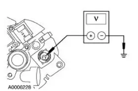
| A2 CHECK THE GENERATOR OUTPUT | Yes GO to A3 . No GO to Pinpoint Test B . |
|
|
| A3 CHECK FOR CURRENT DRAINS | Yes REPAIR as necessary. TEST the system for normal operation. No GO to A4 |
|
|
| A4 CHECK FOR CURRENT DRAINS WHICH SHUT OFF WHEN THE BATTERY IS DISCONNECTED | Yes REPAIR as necessary. TEST the system for normal operation. No GO to Pinpoint Test B . |
|
PINPOINT TEST B: THE CHARGING SYSTEM WARNING INDICATOR IS ON WITH THE ENGINE RUNNING (THE BATTERY VOLTAGE DOES NOT INCREASE)
| Test Step | Result / Action to Take |
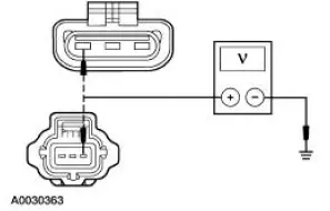
| B1 CHECK GENERATOR B+ CIRCUIT 38 (BK/OG) | Yes GO to B2 . No REPAIR the circuit. TEST the system for normal operation. |
|
|
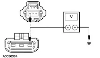
| B2 CHECK GENERATOR A CIRCUIT 36 (YE/WH) | Yes GO to B3 . No REPAIR the circuit. TEST the system for normal operation. |
|
|
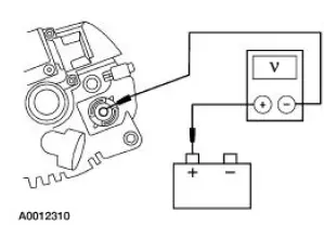
| B3 CHECK I CIRCUIT 904 (LG/RD) FOR AN OPEN | Yes GO to B4 . No REPAIR the circuit. TEST the system for normal operation. |
|
|
| B4 CHECK FOR VOLTAGE DROP IN B+ CIRCUIT 38 (YE/WH) | Yes INSTALL a new generator. REFER to Section . TEST the system for normal operation. No REPAIR high resistance in the B+ circuit 38 (BK/OG). TEST the system for normal operation. |
|
PINPOINT TEST C: THE SYSTEM OVERCHARGES (THE BATTERY VOLTAGE IS GREATER THAN 15.5 VOLTS)
| Test Step | Result / Action to Take |
| C1 CHECK FOR VOLTAGE DROP IN A CIRCUIT 36 (YE/WH) | Yes GO to C2 . No REPAIR the high resistance in A circuit 36 (YE/WH). TEST the system for normal operation. |
|
|
| C2 CHECK GENERATOR AND BATTERY GROUND CONNECTIONS | Yes INSTALL a new generator. REFER to Section. TEST the system for normal operation. No REPAIR ground connections as necessary. TEST the system for normal operation. |
|
PINPOINT TEST D: THE CHARGING SYSTEM WARNING INDICATOR IS ON WITH THE ENGINE RUNNING AND THE BATTERY INCREASES VOLTAGE
| Test Step | Result / Action to Take |
| D1 CHECK I CIRCUIT 904 (LG/RD) FOR A SHORT TO GROUND | Yes REPAIR circuit 904 (LG/RD) for a short to ground. TEST the system for normal operation. No INSTALL a new generator. REFER to Section. TEST the system for normal operation. |
|
PINPOINT TEST E: THE CHARGING SYSTEM WARNING INDICATOR IS OFF WITH THE IGNITION SWITCH IN THE RUN POSITION AND THE ENGINE OFF
| Test Step | Result / Action to Take |
| E1 CHECK THE CHARGING SYSTEM WARNING INDICATOR LAMP | Yes INSTALL a new generator. REFER to Section. TEST the system for normal operation. No REFER to Section for diagnosis and testing of the instrument cluster |
|
PINPOINT TEST F: THE CHARGING SYSTEM WARNING INDICATOR LAMP FLICKERS OR IS INTERMITTENT
| Test Step | Result / Action to Take |
| F1 CHECK FOR LOOSE CONNECTIONS | Yes GO to F2 . No REPAIR as necessary. TEST the system for normal operation. |
|
|
| F2 CHECK FUSE | Yes REPAIR loose fuse connections as necessary. TEST the system for normal operation. No GO to F3 . |
|
|
| F3 CHECK A CIRCUIT 36 (YE/WH) CONNECTIONS | Yes REFER to Section. TEST the system for normal operation. No REPAIR loose connection(s) in circuits. TEST the system for normal operation. |
|
PINPOINT TEST G: THE GENERATOR IS NOISY
| Test Step | Result / Action to Take |
| G1 CHECK FOR ACCESSORY DRIVE NOISE | Yes GO to G2 . No REPAIR as necessary. REFER to Section for diagnosis and testing of the accessory drive system. TEST the system for normal operation. |
|
|
| G2 CHECK GENERATOR MOUNTING | Yes GO to G3 . No REPAIR as necessary. TEST the system for normal operation. |
|
|
| G3 CHECK GENERATOR FOR ELECTRICAL NOISE | Yes GO to G4 . No INSTALL a new generator. REFER to Section. TEST the system for normal operation. |
|
|
| G4 CHECK GENERATOR FOR MECHANICAL NOISE | Yes INSTALL a new generator. REFER to Section. TEST the system for normal operation. No REFER to Section to diagnose the source of engine noise. |
|
PINPOINT TEST H: RADIO INTERFERENCE
| Test Step | Result / Action to Take |
| H1 VERIFY GENERATOR IS SOURCE OF RADIO INTERFERENCE | Yes REFER to Section for diagnosis and testing of the in-vehicle entertainment system. No INSTALL a new generator. REFER to Section. TEST the system for normal operation. |
|
 Inspection and Verification
WARNING: Batteries contain sulfuric acid. Avoid contact with
skin, eyes, or clothing.
Also, shield your eyes when working near batteries to protect against
possible splashing of the
acid so ...
 Component Tests
Battery-Load Test
1. With the engine running, turn the A/C on, the blower motor on high
speed and the headlamps
on high beam.
2. Increase the engine speed to approximately 2,000 rpm. The vol ...
Other materials:
Exterior mirrors
Power Exterior Mirrors
WARNING: Do not adjust the mirror while your vehicle is in
motion.
A. Left mirror
B. Off
C. Right mirror
To adjust your mirrors:
1. Select the mirror you want to adjust.
2. Move the control in the direction you want to tilt the mirror.
...
Installation
1. CAUTION: To prevent refrigerant system contamination, do not allow
dirt or other
foreign materials to enter the A/C compressor.
Clean the A/C compressor nose area.
2. Place the shaft seal on the special tool. Lubricate the shaft seal and the
special tool ...
Fuel System (Description and Operation)
Component Location
WARNING: Do not smoke or carry lighted tobacco or open flame of any
type when
working on or near any fuel-related components. Highly flammable mixtures are
always present
and may be ignited, resulting in possible personal injury ...
