Ford Mustang (1999-2004) Service Manual: Pinpoint Tests
CAUTION: Before removing and installing the GEM or its connectors, disconnect the battery. Failure to follow this caution will result in the GEM storing many erroneous DTCs and may result in the GEM exhibiting erratic operation after installation.
CAUTION: Be careful when probing the central junction box (CJB), battery junction box (BJB), or any connectors. Damage will result to the connector receptacle if the probe being used is too large.
CAUTION: Electronic modules are sensitive to static electrical charges. If exposed to these charges, damage may result.
NOTE: If continuous DTCs are recorded and the symptom is not present when carrying out the pinpoint tests, an intermittent concern may be the cause. Always check for loose connections and corroded terminals.
NOTE: Complete the entire pinpoint test related to the symptom before installing a new GEM.
PINPOINT TEST A: NO COMMUNICATION WITH THE GENERIC ELECTRONIC MODULE
| Test Step | Result / Action to Take |
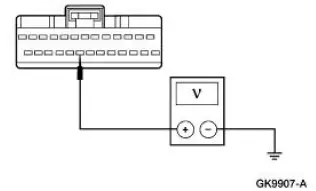
| CAUTION: Use the correct probe adapter(s) when making measurements. Failure to use the correct probe adapter(s) may damage the connector. | |
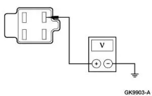
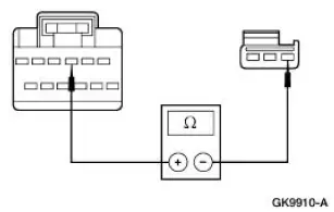
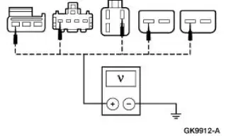
| A1 GENERIC ELECTRONIC MODULE (GEM) POWER SUPPLY | Yes GO to A2 . No REPAIR the circuit(s) in question. TEST the system for normal operation. |
|
|
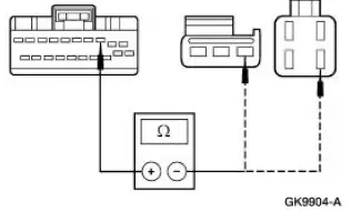
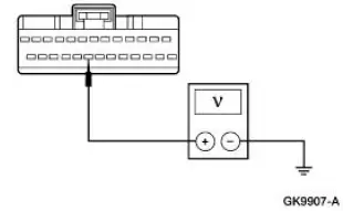
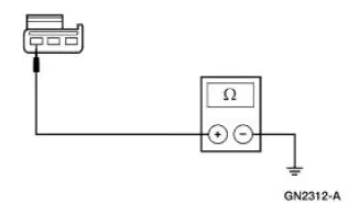
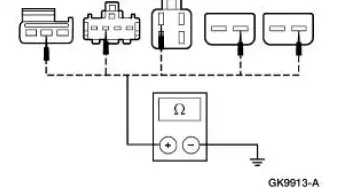
| A2 CHECK THE GEM GROUND CIRCUIT 397 (BK/WH) FOR OPEN | Yes GO to A3 . No REPAIR the circuit(s) in question. TEST the system for normal operation. |
|
|
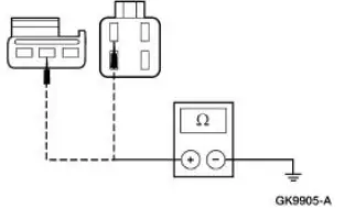
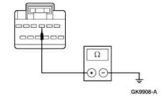
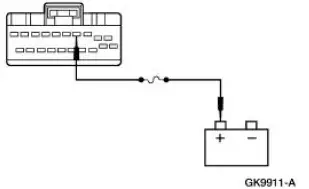
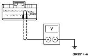
| A3 CHECK CIRCUIT 397 (BK/WH) FOR SHORT TO POWER | Yes REPAIR the circuit. TEST the system for normal operation. No REFER to Section |
|
|
PINPOINT TEST B: THE COURTESY LAMPS ARE INOPERATIVE
| Test Step | Result / Action to Take |
| B1 CHECK IGNITION STATES | Yes GO to B2 . No For key-in-ignition concerns, REFER to Section |
|
|
| B2 CHECK THE DOOR AJAR INPUT TO THE GEM | Yes GO to B3 . No REFER to Section |
|
|
| B3 CHECK THE DOME LAMP SWITCH STATUS INPUT TO THE GEM - MONITOR THE GEM PID DOMESW | Yes GO to B4 . No GO to B13 . |
|
|
| B4 CHECK THE LUGGAGE COMPARTMENT LID AJAR INPUT TO THE GEM - MONITOR THE GEM PID DECKLID | Yes GO to B5 . No GO to B16 |
|
|
| B5 CHECK THE COURTESY LAMP CIRCUITS | Yes GO to B12 . No GO to B6 . |
|
|
| B6 CHECK THE GEM CONTROL OF THE COURTESY LAMPS | Yes INSTALL a new GEM. For additional information, REFER to Section. REPEAT the self-test. CLEAR the DTCs. No GO to B7 . |
|
|
| B7 CHECK THE GEM FOR AN INTERNAL FAULT | Yes GO to B8 . No INSTALL a new GEM. For additional information, REFER to Section. REPEAT the self-test. CLEAR the DTCs |
|
|
| B8 CHECK CIRCUIT 1034 (BK/WH) FOR VOLTAGE | Yes GO to B11 . No GO to B9 . |
|
|
| B9 CHECK CIRCUIT 1006 (DG/WH) FOR OPEN | Yes GO to B10 . No REPAIR the circuit. REPEAT the self-test. CLEAR the DTCs. |
NOTE: Verify battery voltage at CJB Fuse 7 (20A) before carrying out this test.
|
|
| B10 CHECK CIRCUIT 1034 (BK/WH) FOR OPEN | Yes INSTALL a new GEM. For additional information, REFER to Section. REPEAT the self-test. CLEAR the DTCs. No REPAIR the circuit. REPEAT the self-test. CLEAR the DTCs. |
|
|
| B11 CHECK CIRCUIT 1205 (BK) FOR OPEN | Yes INSTALL a new dome/map lamp assembly. For additional information, REFER to Lamp Assembly- Map/Dome . No REPAIR the circuit. REPEAT the self-test. CLEAR the DTCs. |
|
|
| B12 CHECK CIRCUIT 1034 (BK/WH) FOR SHORT TO BATTERY | Yes REPAIR the circuit. REPEAT the self-test. CLEAR the DTCs. No INSTALL a new GEM. For additional information, REFER to Section. REPEAT the self-test. CLEAR the DTCs. |
|
|
| B13 CHECK THE COURTESY LAMP OPERATION - MONITOR THE GEM PID DOMESW | Yes GO to B15 . No GO to B14 . |
|
|
| B14 CHECK CIRCUIT 706 (GY) FOR OPEN | Yes INSTALL a new GEM. For additional information, REFER to Section. REPEAT the self-test. CLEAR the DTCs. No REPAIR the circuit. REPEAT the self-test. CLEAR the DTCs. |
|
|
| B15 CHECK CIRCUIT 706 (GY) FOR SHORT TO BATTERY | Yes REPAIR the circuit. REPEAT the self-test. CLEAR the DTCs. No INSTALL a new GEM. For additional information, REFER to Section. REPEAT the self-test. CLEAR the DTCs. |
|
|
| B16 CHECK CIRCUIT 486 (BN/WH) FOR OPEN OR SHORT TO GROUND - MONITOR THE GEM PID DECKLID | Yes GO to B17 . No GO to B19 . |
|
|
| B17 CHECK LUGGAGE COMPARTMENT SOLENOID FOR SHORT TO GROUND | Yes INSTALL a new luggage compartment solenoid. For additional information, REFER to Section. REPEAT the selftest. CLEAR the DTC. No GO to B18 . |
|
|
| B18 CHECK CIRCUIT 486 (BN/WH) FOR SHORT TO GROUND | Yes INSTALL a new GEM. For additional information, REFER to Section. REPEAT the self-test. CLEAR the DTCs. No REPAIR the circuit. REPEAT the self-test. CLEAR the DTCs. |
|
|
| B19 CHECK CIRCUIT 486 (BN/WH) FOR AN OPEN - MONITOR GEM PID DECKLID | Yes GO to B21 . No GO to B20 . |
|
|
| B20 CHECK CIRCUIT 486 (BN/WH) FOR OPEN | Yes INSTALL a new GEM. For additional information, REFER to Section. REPEAT the self-test. CLEAR the DTCs. No REPAIR the circuit. REPEAT the self-test. CLEAR the DTCs. |
|
|
| B21 CHECK GROUND CIRCUIT 1205 (BK) FOR OPEN | Yes INSTALL a new luggage compartment solenoid. For additional information, REFER to Section. REPEAT the selftest. CLEAR the DTCs. No REPAIR the circuit. REPEAT the self-test. CLEAR the DTCs. |
|
PINPOINT TEST C: THE DEMAND LIGHTING IS INOPERATIVE
| Test Step | Result / Action to Take |
| C1 CHECK GEM SUPPLIED POWER TO THE DEMAND LAMPS | Yes GO to C8 . No GO to C2 . |
|
|
| C2 CHECK IGNITION STATES | Yes GO to C3 . No For key-in-ignition concerns, REFER to Section |
|
|
| C3 CHECK DRIVER AND PASSENGER DOOR AJAR INPUTS TO THE GEM | Yes GO to C4 . No REFER to Section |
|
|
| C4 CHECK INTERIOR LAMP SWITCH INPUT TO THE GEM - MONITOR GEM PID DOMESW | Yes GO to C5 . No GO to Pinpoint Test B . |
|
|
| C5 CHECK THE LUGGAGE COMPARTMENT LID AJAR INPUT TO THE GEM - MONITOR THE GEM PID DECKLID | Yes GO to C6 . No GO to Pinpoint Test B . |
|
|
| C6 CHECK CIRCUIT 705 (LG/OG) FOR OPEN | Yes GO to C7 . No REPAIR the circuit. REPEAT the self-test. CLEAR the DTCs. |
|
|
| C7 CHECK CIRCUIT 1006 (DG/WH) FOR OPEN | Yes INSTALL a new GEM. For additional information, REFER to Section. REPEAT the self-test. CLEAR the DTCs. No REPAIR the circuit. REPEAT the self-test. CLEAR the DTCs. |
NOTE: Verify battery voltage at CJB Fuse 7 (20A) before carrying out this test.
|
|
| C8 CHECK CIRCUIT 705 (LG/OG) FOR VOLTAGE AT INOPERATIVE DEMAND LAMP | Yes GO to C9 . No REPAIR the circuit in question. REPEAT the self-test. CLEAR the DTCs. |
|
|
| C9 CHECK CIRCUIT 1205 (BK) FOR OPEN AT INOPERATIVE DEMAND LAMP | Yes INSTALL a new demand lamp assembly. REPEAT the self-test. CLEAR the DTCs. No REPAIR the circuit in question. REPEAT the self-test. CLEAR the DTCs. |
|
PINPOINT TEST D: THE ILLUMINATED ENTRY IS INOPERATIVE WHEN USING THE REMOTE TRANSMITTER
| Test Step | Result / Action to Take |
| D1 CHECK THE REMOTE TRANSMITTER INPUT TO THE GEM | Yes GO to D2 . No REFER to Section |
|
|
| D2 CHECK OPERATION OF ILLUMINATED ENTRY WITHOUT REMOTE TRANSMITTER | Yes INSTALL a new GEM. For additional information, REFER to Section. REPEAT the self-test. CLEAR the DTCs. No GO to Pinpoint Test B |
|
PINPOINT TEST E: THE BATTERY SAVER DOES NOT DEACTIVATE AFTER TIMEOUT
| Test Step | Result / Action to Take |
| E1 CHECK THE GEM CONTROL OF THE BATTERY SAVER FUNCTION - TRIGGER THE GEM ACTIVE COMMAND BATT SAVR ON | Yes INSTALL a new GEM. For additional information, REFER to Section. REPEAT the self-test. CLEAR the DTCs. No GO to E2 . |
|
|
| E2 CHECK CIRCUITS 1034 (BK/WH), AND 705 (LG/OG), FOR SHORT TO BATTERY | Yes REPAIR the circuit in question. REPEAT the self-test. CLEAR the DTCs. No INSTALL a new GEM. For additional information, REFER to Section. REPEAT the self-test. CLEAR the DTCs. |
|
 Inspection and Verification
1. The interior lighting system is a generic electronic module (GEM)
controlled system.
2. Verify the customer concern by operating the interior lighting system.
3. Visually inspect for the foll ...
 Lamp Assembly - Map/Dome
Removal
1. Disconnect the battery ground cable.
2. Remove the lamp lens from the lamp assembly.
3. Remove the lamp assembly.
1. Remove the screws.
2. Remove the lamp assembly.
Discon ...
Other materials:
Module Configuration
Module Configuration (Diagnosis and Testing)
Special Tool(s)
Worldwide Diagnostic System
(WDS)
418-F224
New Generation STAR (NGS)
Tester
418-F052 or equivalent
diagnostic tool
Principles of Operation
Some modules must be programme ...
Disassembly
NOTE: The steering gear is serviceable as either a long or short rack
assembly. This procedure covers
the removal and installation of the components not supplied with a short rack
assembly. On short rack
assembly only the front wheel spindle tie-rods and fro ...
Inspection and Assembly Requirements - Following an
A/C
Compressor Failure
CAUTION: To prevent refrigerant system contamination and possible
failure of the new
A/C compressor, carry out the following procedures.
1. NOTE: A dirty A/C evaporator core orifice or a condenser to
evaporator tube containing black
refrigerant oil and parti ...
