Ford Mustang Service Manual: Interior Lighting (Diagnosis and Testing)
Interior Lighting (Diagnosis and Testing)
Refer to Wiring Diagrams Cell 111 , Remote Control Alarm and Lock System for schematic and connector information.
Refer to Wiring Diagrams Cell 59 , Generic Electronic Module for schematic and connector information.
Refer to Wiring Diagrams Cell 89 , Courtesy Lamps for schematic and connector information.
Special Tool(s)
![]() |
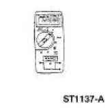
73 Digital Multimeter or equivalent 105-R0051 |
![]() |
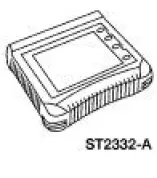
Worldwide Diagnostic System (WDS) 418-F224, New Generation STAR (NGS) Tester 418-F052, or equivalent scan tool |
Principles of Operation
Battery Saver
The battery saver feature provides automatic shut-off of power to demand and courtesy lamp circuitry.
When the generic electronic module (GEM) detects the ignition switch circuits are in the key OFF or removed ignition key positions, power will be disabled after individual time-out periods of 30 minutes for the demand lamps, and 10 minutes for the courtesy lamps. However, the time-out period for the courtesy lamps changes to 30 minutes when the GEM detects that the luggage compartment lid is ajar by means of the luggage compartment lid ajar circuit, or if the dome lamp is switched on by means of the dome lamp circuit. When the GEM detects that the ignition switch is in the RUN, ACC, or START positions, the battery saver feature is disabled.
The battery saver timer for the demand lamps is reset when the GEM detects that the ignition switch is in the OFF or key out positions or when the GEM detects any one of the following conditions:
- the driver or passenger door becomes ajar, as detected by the door ajar circuit
- the luggage compartment lid becomes ajar, as detected by the luggage compartment lid ajar circuit
- the dome lamp switch is activated, as detected by the dome lamp switch circuit
The battery saver timer for the courtesy lamps is reset when the GEM detects that the ignition switch is in the OFF or key out positions or when the GEM detects the driver or passenger door becomes ajar as detected by the door ajar circuit. For vehicles equipped with the remote keyless entry feature, any signal the GEM detects when a valid remote transmitter button is depressed will reset both the demand and courtesy lamp battery saver timers. This battery saver relay then restores power to both the demand and courtesy lamp circuits.
Base Courtesy and Extended Lighting
The base courtesy lighting feature provides interior lighting for the convenience of the vehicle's occupants. The courtesy lamps consist of the map/dome lamps for the coupe and the map lamps for the convertible. All lamps designated as courtesy lamps will be illuminated whenever the GEM detects that the driver or passenger doors become ajar, by means of the driver or passenger door ajar circuits.
The courtesy lamps will also be illuminated when the GEM detects that the dome lamp switch has been activated, by means of the dome lamp switch circuit.
The extended courtesy lighting feature provides temporary extended illumination of the courtesy lamps after the customer has entered the vehicle. The courtesy lamps will remain illuminated for 25 seconds after the GEM detects that the driver and passenger doors are closed, as detected by the door ajar circuits. The extended courtesy lighting feature will be terminated after the 25 second time-out period, or if the GEM detects that the ignition switch has been moved from the OFF position to either the RUN, ACC, or START positions.
Demand Lighting
The GEM does not provide any special features to the demand lighting group with the exception of providing a power source when the battery saver feature is active. The demand lighting group consists of the luggage compartment lamp, the driver and passenger vanity mirror lamps, and the map lamps.
Illuminated Entry with Remote Keyless Entry
The illuminated entry with remote keyless entry feature, provides power to the courtesy lamps when the remote transmitter is used. When the GEM detects that the ignition switch is in the OFF or key out positions, and it detects that a valid remote transmitter unlock button has been depressed, power to the courtesy lamps will be enabled. The courtesy lamp circuit will remain powered until one of the following occurs:
- The GEM detects that the ignition switch has been moved from the OFF, to the RUN, START, or ACC position.
- The GEM detects any valid remote transmitter lock button is depressed.
- The courtesy lamp circuit has been powered for 25 seconds.
If the GEM detects any valid remote transmitter unlock button has been depressed, and the ignition switch is in the OFF or key out position during the 25 second time-out, the courtesy lamp circuits will remain powered for an additional 25 seconds.
Inspection and Verification
1. The interior lighting system is a generic electronic module (GEM) controlled system.
2. Verify the customer concern by operating the interior lighting system.
3. Visually inspect for the following obvious signs of mechanical and electrical damage.
Visual Inspection Chart
Mechanical | Electrical |
|
|
4. If the concern remains after the inspection, connect the scan tool to the data link connector (DLC) located beneath the instrument panel and select the vehicle to be tested from the scan tool menu. If the scan tool does not communicate with the vehicle:
- check that the program card is correctly installed.
- check the connections to the vehicle.
- check the ignition switch position.
5. If the scan tool still does not communicate with the vehicle, refer to the scan tool manual.
6. Carry out the DATA LINK DIAGNOSTIC TEST. If the scan tool responds with:
- CKT914, CKT915 or CKT70 = ALL ECUS NO RESP/NOT EQUIP, refer to Section .
- NO RESP/NOT EQUIP for GEM, go to Pinpoint Test A.
- SYSTEM PASSED, retrieve and record the continuous diagnostic trouble codes (DTCs), erase the continuous DTCs and carry out self-test diagnostics for the GEM.
7. If the DTCs retrieved are related to the concern, go to GEM Diagnostic Trouble Code (DTC) Index to continue diagnostics.
8. If no DTCs related to the concern are retrieved, proceed to Symptom Chart to continue diagnostics.
GEM Diagnostic Trouble Code (DTC) Index
DTC | Description | Source |
B1322 | Driver Door Ajar Circuit Short to Ground | GEM |
B1330 | Passenger Door Ajar Circuit Short to Ground | GEM |
B1334 | Decklid Ajar Rear Door Circuit Short to Ground | GEM |
B1342 | ECU Is Defective | GEM |
B1397 | Power Door unlock Circuit Short to Battery | GEM |
B1405 | Driver Power Window Down Circuit Short to Battery | GEM |
B1408 | Driver Power Window Up Circuit Short to Battery | GEM |
B1410 | Driver Power Window Motor Circuit Failure | GEM |
B1426 | Lamp Safety Belt Circuit Short to Battery | GEM |
B1428 | Lamp Safety Belt Circuit Failure | GEM |
B1431 | Wiper Brake/Run Relay Circuit Failure | GEM |
B1432 | Wiper Brake/Run Relay Circuit Short to Battery | GEM |
B1434 | Wiper Hi/Low Speed Relay Coil Circuit Failure | GEM |
B1436 | Wiper Hi/Low Speed Relay Coil Circuit Short to Battery | GEM |
B1438 | Wiper Mode Select Switch Circuit Failure | GEM |
B1441 | Wiper Mode Select Switch Circuit Short to Ground | GEM |
B1446 | Wiper Park Sense Circuit Failure | GEM |
B1448 | Wiper Park Sense Circuit Short to Battery | GEM |
B1450 | Wiper Wash/Delay Switch Circuit Failure | GEM |
B1453 | Wiper Wash/Delay Switch Circuit Short to Ground | GEM |
B1458 | Wiper Washer Pump Motor Relay Circuit Failure | GEM |
B1460 | Wiper Washer Pump Motor Relay Coil Circuit Short to Battery | GEM |
B1462 | Safety Belt Switch Circuit Failure | GEM |
B1466 | Wiper Hi/Low Speed Not Switching | GEM |
B1473 | Wiper Low Speed Circuit Motor Failure | GEM |
B1476 | Wiper High Speed Circuit Motor Failure | GEM |
B1551 | Decklid Release Circuit Failure | GEM |
B1553 | Decklid Release Circuit Short to Battery | GEM |
B1555 | Ignition Run/Start Circuit Failure | GEM |
B1687 | Lamp Dome Input Circuit Short to Battery | GEM |
B2486 | LF Side Repeater Lamp Output Circuit Failure | GEM |
B2488 | RF Side Repeater Lamp Output Circuit Failure | GEM |
C1189 | Brake Fluid Level Sensor Input Short Circuit to Ground | GEM |
C1223 | Lamp Brake Warning Output Circuit Failure | GEM |
C1225 | Lamp Brake Warning Output Circuit Short to Battery | GEM |
Symptom Chart
Condition | Possible Sources | Action |
|
|
|
|
|
|
|
|
|
|
|
|
|
|
|
Pinpoint Tests
CAUTION: Before removing and installing the GEM or its connectors, disconnect the battery. Failure to follow this caution will result in the GEM storing many erroneous DTCs and may result in the GEM exhibiting erratic operation after installation.
CAUTION: Be careful when probing the central junction box (CJB), battery junction box (BJB), or any connectors. Damage will result to the connector receptacle if the probe being used is too large.
CAUTION: Electronic modules are sensitive to static electrical charges. If exposed to these charges, damage may result.
NOTE: If continuous DTCs are recorded and the symptom is not present when carrying out the pinpoint tests, an intermittent concern may be the cause. Always check for loose connections and corroded terminals.
NOTE: Complete the entire pinpoint test related to the symptom before installing a new GEM.
PINPOINT TEST A: NO COMMUNICATION WITH THE GENERIC ELECTRONIC MODULE
Test Step | Result / Action to Take |
CAUTION: Use the correct probe adapter(s) when making measurements. Failure to use the correct probe adapter(s) may damage the connector. | |
A1 GENERIC ELECTRONIC MODULE (GEM) POWER SUPPLY | Yes GO to A2 . No REPAIR the circuit(s) in question. TEST the system for normal operation. |
|
|
A2 CHECK THE GEM GROUND CIRCUIT 397 (BK/WH) FOR OPEN | Yes GO to A3 . No REPAIR the circuit(s) in question. TEST the system for normal operation. |
|
|
A3 CHECK CIRCUIT 397 (BK/WH) FOR SHORT TO POWER | Yes REPAIR the circuit. TEST the system for normal operation. No REFER to Section |
|
PINPOINT TEST B: THE COURTESY LAMPS ARE INOPERATIVE
Test Step | Result / Action to Take |
B1 CHECK IGNITION STATES | Yes GO to B2 . No For key-in-ignition concerns, REFER to Section |
|
|
B2 CHECK THE DOOR AJAR INPUT TO THE GEM | Yes GO to B3 . No REFER to Section |
|
|
B3 CHECK THE DOME LAMP SWITCH STATUS INPUT TO THE GEM - MONITOR THE GEM PID DOMESW | Yes GO to B4 . No GO to B13 . |
|
|
B4 CHECK THE LUGGAGE COMPARTMENT LID AJAR INPUT TO THE GEM - MONITOR THE GEM PID DECKLID | Yes GO to B5 . No GO to B16 |
|
|
B5 CHECK THE COURTESY LAMP CIRCUITS | Yes GO to B12 . No GO to B6 . |
|
|
B6 CHECK THE GEM CONTROL OF THE COURTESY LAMPS | Yes INSTALL a new GEM. For additional information, REFER to Section. REPEAT the self-test. CLEAR the DTCs. No GO to B7 . |
|
|
B7 CHECK THE GEM FOR AN INTERNAL FAULT | Yes GO to B8 . No INSTALL a new GEM. For additional information, REFER to Section. REPEAT the self-test. CLEAR the DTCs |
|
|
B8 CHECK CIRCUIT 1034 (BK/WH) FOR VOLTAGE | Yes GO to B11 . No GO to B9 . |
|
|
B9 CHECK CIRCUIT 1006 (DG/WH) FOR OPEN | Yes GO to B10 . No REPAIR the circuit. REPEAT the self-test. CLEAR the DTCs. |
NOTE: Verify battery voltage at CJB Fuse 7 (20A) before carrying out this test.
|
|
B10 CHECK CIRCUIT 1034 (BK/WH) FOR OPEN | Yes INSTALL a new GEM. For additional information, REFER to Section. REPEAT the self-test. CLEAR the DTCs. No REPAIR the circuit. REPEAT the self-test. CLEAR the DTCs. |
|
|
B11 CHECK CIRCUIT 1205 (BK) FOR OPEN | Yes INSTALL a new dome/map lamp assembly. For additional information, REFER to Lamp Assembly- Map/Dome . No REPAIR the circuit. REPEAT the self-test. CLEAR the DTCs. |
|
|
B12 CHECK CIRCUIT 1034 (BK/WH) FOR SHORT TO BATTERY | Yes REPAIR the circuit. REPEAT the self-test. CLEAR the DTCs. No INSTALL a new GEM. For additional information, REFER to Section. REPEAT the self-test. CLEAR the DTCs. |
|
|
B13 CHECK THE COURTESY LAMP OPERATION - MONITOR THE GEM PID DOMESW | Yes GO to B15 . No GO to B14 . |
|
|
B14 CHECK CIRCUIT 706 (GY) FOR OPEN | Yes INSTALL a new GEM. For additional information, REFER to Section. REPEAT the self-test. CLEAR the DTCs. No REPAIR the circuit. REPEAT the self-test. CLEAR the DTCs. |
|
|
B15 CHECK CIRCUIT 706 (GY) FOR SHORT TO BATTERY | Yes REPAIR the circuit. REPEAT the self-test. CLEAR the DTCs. No INSTALL a new GEM. For additional information, REFER to Section. REPEAT the self-test. CLEAR the DTCs. |
|
|
B16 CHECK CIRCUIT 486 (BN/WH) FOR OPEN OR SHORT TO GROUND - MONITOR THE GEM PID DECKLID | Yes GO to B17 . No GO to B19 . |
|
|
B17 CHECK LUGGAGE COMPARTMENT SOLENOID FOR SHORT TO GROUND | Yes INSTALL a new luggage compartment solenoid. For additional information, REFER to Section. REPEAT the selftest. CLEAR the DTC. No GO to B18 . |
|
|
B18 CHECK CIRCUIT 486 (BN/WH) FOR SHORT TO GROUND | Yes INSTALL a new GEM. For additional information, REFER to Section. REPEAT the self-test. CLEAR the DTCs. No REPAIR the circuit. REPEAT the self-test. CLEAR the DTCs. |
|
|
B19 CHECK CIRCUIT 486 (BN/WH) FOR AN OPEN - MONITOR GEM PID DECKLID | Yes GO to B21 . No GO to B20 . |
|
|
B20 CHECK CIRCUIT 486 (BN/WH) FOR OPEN | Yes INSTALL a new GEM. For additional information, REFER to Section. REPEAT the self-test. CLEAR the DTCs. No REPAIR the circuit. REPEAT the self-test. CLEAR the DTCs. |
|
|
B21 CHECK GROUND CIRCUIT 1205 (BK) FOR OPEN | Yes INSTALL a new luggage compartment solenoid. For additional information, REFER to Section. REPEAT the selftest. CLEAR the DTCs. No REPAIR the circuit. REPEAT the self-test. CLEAR the DTCs. |
|
PINPOINT TEST C: THE DEMAND LIGHTING IS INOPERATIVE
Test Step | Result / Action to Take |
C1 CHECK GEM SUPPLIED POWER TO THE DEMAND LAMPS | Yes GO to C8 . No GO to C2 . |
|
|
C2 CHECK IGNITION STATES | Yes GO to C3 . No For key-in-ignition concerns, REFER to Section |
|
|
C3 CHECK DRIVER AND PASSENGER DOOR AJAR INPUTS TO THE GEM | Yes GO to C4 . No REFER to Section |
|
|
C4 CHECK INTERIOR LAMP SWITCH INPUT TO THE GEM - MONITOR GEM PID DOMESW | Yes GO to C5 . No GO to Pinpoint Test B . |
|
|
C5 CHECK THE LUGGAGE COMPARTMENT LID AJAR INPUT TO THE GEM - MONITOR THE GEM PID DECKLID | Yes GO to C6 . No GO to Pinpoint Test B . |
|
|
C6 CHECK CIRCUIT 705 (LG/OG) FOR OPEN | Yes GO to C7 . No REPAIR the circuit. REPEAT the self-test. CLEAR the DTCs. |
|
|
C7 CHECK CIRCUIT 1006 (DG/WH) FOR OPEN | Yes INSTALL a new GEM. For additional information, REFER to Section. REPEAT the self-test. CLEAR the DTCs. No REPAIR the circuit. REPEAT the self-test. CLEAR the DTCs. |
NOTE: Verify battery voltage at CJB Fuse 7 (20A) before carrying out this test.
|
|
C8 CHECK CIRCUIT 705 (LG/OG) FOR VOLTAGE AT INOPERATIVE DEMAND LAMP | Yes GO to C9 . No REPAIR the circuit in question. REPEAT the self-test. CLEAR the DTCs. |
|
|
C9 CHECK CIRCUIT 1205 (BK) FOR OPEN AT INOPERATIVE DEMAND LAMP | Yes INSTALL a new demand lamp assembly. REPEAT the self-test. CLEAR the DTCs. No REPAIR the circuit in question. REPEAT the self-test. CLEAR the DTCs. |
|
PINPOINT TEST D: THE ILLUMINATED ENTRY IS INOPERATIVE WHEN USING THE REMOTE TRANSMITTER
Test Step | Result / Action to Take |
D1 CHECK THE REMOTE TRANSMITTER INPUT TO THE GEM | Yes GO to D2 . No REFER to Section |
|
|
D2 CHECK OPERATION OF ILLUMINATED ENTRY WITHOUT REMOTE TRANSMITTER | Yes INSTALL a new GEM. For additional information, REFER to Section. REPEAT the self-test. CLEAR the DTCs. No GO to Pinpoint Test B |
|
PINPOINT TEST E: THE BATTERY SAVER DOES NOT DEACTIVATE AFTER TIMEOUT
Test Step | Result / Action to Take |
E1 CHECK THE GEM CONTROL OF THE BATTERY SAVER FUNCTION - TRIGGER THE GEM ACTIVE COMMAND BATT SAVR ON | Yes INSTALL a new GEM. For additional information, REFER to Section. REPEAT the self-test. CLEAR the DTCs. No GO to E2 . |
|
|
E2 CHECK CIRCUITS 1034 (BK/WH), AND 705 (LG/OG), FOR SHORT TO BATTERY | Yes REPAIR the circuit in question. REPEAT the self-test. CLEAR the DTCs. No INSTALL a new GEM. For additional information, REFER to Section. REPEAT the self-test. CLEAR the DTCs. |
|
Interior Lighting
Interior Lighting
The interior lighting system consists of the following:
map/dome lamp assembly
rear-high mount/cargo lamp assembly
dimmer switch
door ajar switch (located on the door latc ...
Principles of Operation
Battery Saver
The battery saver feature provides automatic shut-off of power to demand
and courtesy lamp circuitry.
When the generic electronic module (GEM) detects the i ...
Other materials:
System menu features
Your system offers many menu features, such as allowing you to adjust the touchscreen
brightness, time and language, feedback and system settings. You can access these
options by pressing the MENU hard button.
...
Manifold Gauge Set Connection
Climate Control System (Description and Operation)
WARNING: To avoid accidental deployment and possible injury, the air
bag system
backup power supply must be depleted before repairing any climate control
components. To
deplete the backup power supply, disco ...
Removal
Removal
All vehicles
1. Remove the air intake scoop bracket. For additional information, refer to
Section.
2. Remove the RH valve cover. For additional information, refer to Valve Cover
RH in this section.
3. Remove the Hydro-Boost brake booster. For addit ...