Ford Mustang (1999-2004) Service Manual: Powertrain Control Module (PCM)
Removal
1. Disconnect the battery ground cable. For additional information, refer to Section.
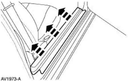
2. Remove the RH front door scuff plate.
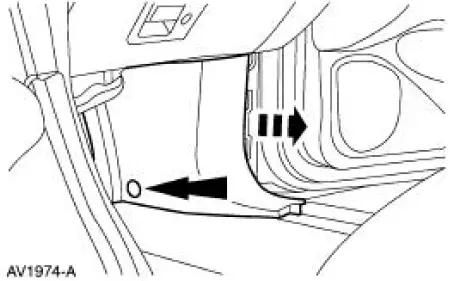
3. Remove the RH cowl side trim panel.
- Remove the pin-type retainer.
- Remove the panel.
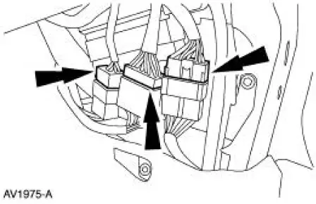
4. Disconnect the connectors and position them aside.
5. Remove the bolts and the bracket.
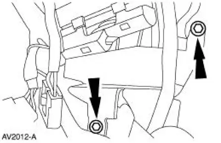
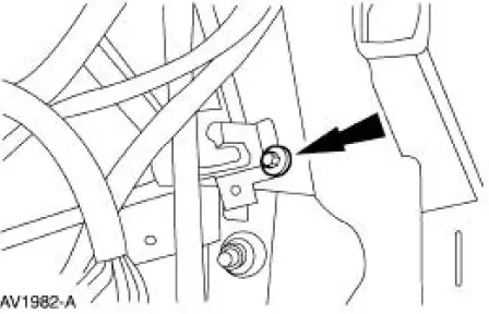
6. Loosen the bolt and remove the connector.
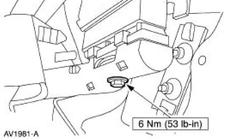
7. Remove the bolt and the powertrain control module (PCM).
Installation
1. To install, reverse the removal procedure.
 Crankshaft Position (CKP) Sensor - 4.6L
Removal
1. Disconnect the battery ground cable. For additional information,
refer to Section.
2. Remove the A/C compressor. For additional information, refer to
Section.
3. Remove the cr ...
 Throttle Position (TP) Sensor
Removal
NOTE: The 3.8L engine is shown; the 4.6L (2V) is similar.
1. Disconnect the battery ground cable. For additional information,
refer to Section.
2. Remove the throttle position (TP) s ...
Other materials:
Pump - CII
Special Tool(s)
Teflon Seal Replacer Set
211D027 (D90P-3517-A) or
equivalent
Removal and Installation
1. Disconnect the power steering hose. Remove and discard the seal ring.
2. Disconnect the power steering hose.
3. Remove the pulley.
...
Interior Trim Codes
The interior trim codes are listed below. The first letter/number is for the
interior fabric. The second
letter is for the interior color.
9 - Quantum/Rhodes cloth (base coupe)
A - Link weave cloth (Mach One)
M - Nudo Leather (Cobra)
T - Lea cloth with ...
Navigation controls
Type 1
WARNING: Driving while distracted can result in loss of vehicle
control, crash and injury. We strongly recommend that you use
extreme caution when using any device that may take your focus off
the road. Your primary responsibility is the safe operation ...
