Ford Mustang (1999-2004) Service Manual: Removal
CAUTION: Suspension fasteners are critical parts because they affect performance of vital components and systems and their failure can result in major service expense. A new part with the same part number must be installed if installation becomes necessary. If substitution is necessary, the part must be of the same finish and property class. Torque values must be used as specified during reassembly to make sure of correct retention of these parts.
All vehicles
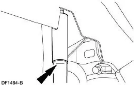
1. Mark the rear shock absorber (18125) relative to the protective sleeve with the vehicle in a static, level ground position (curb height).
2. Raise the vehicle.
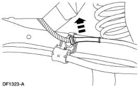
3. Disconnect the anti-lock sensor wire.
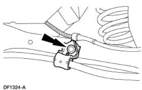
4. Remove the bolt and the parking brake cable bracket. Discard the bolt.
Vehicles equipped with a 4.6L 2V engine
5. Remove the stabilizer bar (5A772). For additional information, refer to Stabilizer Bar in this section.
All vehicles
6. Support the differential housing with a jack stand.
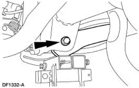
7. Position the special tool 014-00942 under the rear lower suspension arm and bushing-to-axle pivot bolt.
8. Remove and discard the pivot bolt and nut.
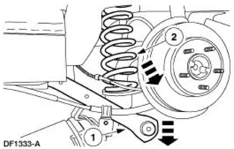
9. Remove the spring (5560).
1. Slowly lower the arm with the special tool 014-00942.
2. Remove the rear spring and the rear spring insulators (5536).
 Spring - Coil
Special Tool(s)
Hi-Lift Jack
014-00942 or Equivalent
...
 Installation
All vehicles
1. NOTE: Inspect the insulators for wear or damage. Install new
insulators if necessary.
Install the upper insulator on the spring.
2. Install the lower insulator on the lower arm.
...
Other materials:
Exhaust Gas Recirculation (EGR) Valve - Mach I
Removal and Installation
1. Remove the air intake scoop. For additional information, refer to
Section.
2. Remove the exhaust gas recirculation (EGR) valve.
1. Disconnect the EGR tube upper fitting.
2. Disconnect the vacuum hose.
3. Remove the tw ...
Oil Filter Adapter
Material
Item
Specification
Super Premium SAE 5W-20
Motor Oil
XO-5W20 QSP or equivalent
WSS-M2C153-
H
Premium Engine Coolant
VC-4A (In Canada CXC-10; In
Oregon VC-5) or equivalent
ESE-M97B44-
A
Removal and Installation
1. ...
Compressor Manifold and Tube Assembly - 3.8L
Material
Item
Specification
PAG Refrigerant Compressor
Oil (R-134a Systems)
F7AZ-19589-DA (Motorcraft YN-
12-C)
WSH-M1C231-
B
Removal and Installation
NOTE: Installation of a new suction accumulator is not required when
repairing the ...
