Ford Mustang (1999-2004) Service Manual: Removal
1. Remove the differential housing cover (4033) and drain the rear axle (4001). For additional information, refer to Differential Housing Cover in this section.
2. CAUTION: Reinstall the differential pinion shaft (4211) and the bolt in the differential case (4204) after removing the axle shafts (4234).
Remove the axle shafts. For additional information, refer to Axle Shaft in this section.
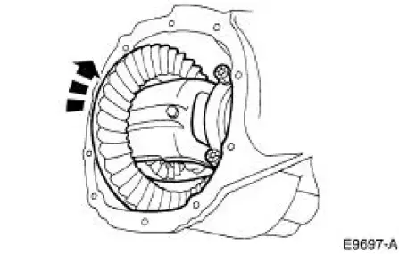
3. Wipe the lubricant from the internal working parts and inspect the parts for wear and damage.
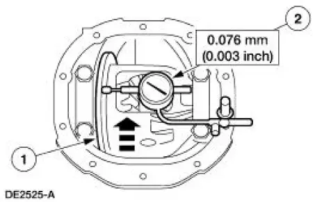
4. Rotate the differential assembly to check for roughness indicating bearing/gear damage.
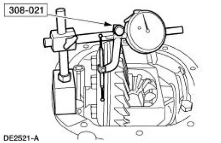
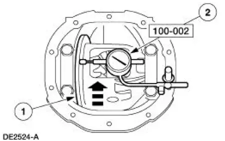
5. Using a suitable dial indicator and the special tool, measure and note the ring gear backface runout.
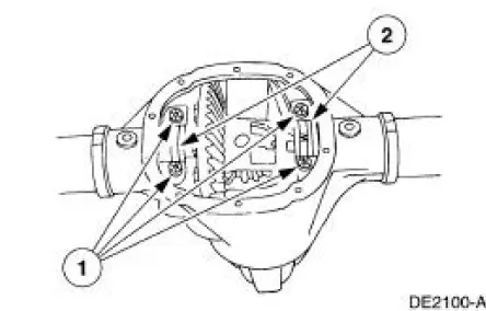
6. CAUTION: Mark the position and location of the bearing caps, as the arrows may not be visible. Always install the bearing caps in their identical locations and positions.
Remove the bearing caps.
1. Remove the bolts.
2. Remove the bearing caps.
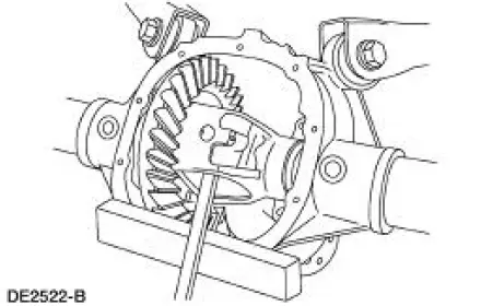
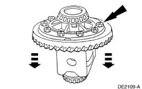
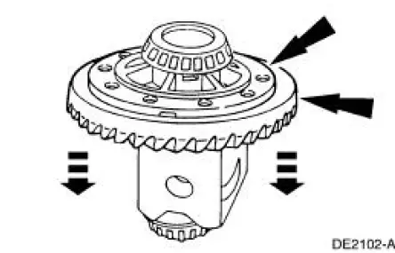
7. WARNING: Do not allow the differential assembly to fall. Failure to follow these instructions may result in personal injury and component damage.
CAUTION: Place a wood block between the pry bar and the differential housing 4010) to protect the machined surface from damage.
Using a pry bar and a wood block, remove the differential assembly from the differential housing.
8. Remove the 10 bolts.
9. CAUTION: Do not damage the threads in the bolt holes.
Insert a punch in the bolt holes, and drive off the ring gear.
10. If the ring gear backface runout measurement, taken at the beginning of this procedure, did not exceed the specification, proceed to the appropriate procedure as necessary: Drive Pinion , Differential Case and Ring Gear-Conventional or Differential Case and Ring Gear-Traction- Lok in this section, or to Installation in this procedure. If the ring gear backface runout measurement, taken at the beginning of this procedure, exceeded the specification, the cause may be a warped ring gear, differential case/differential bearing damage. Proceed as follows to verify the cause of the excessive runout.
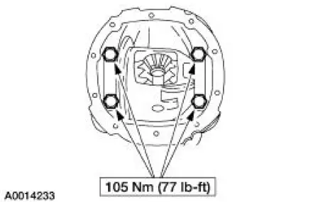
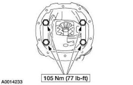
11. Position the differential assembly, including the differential bearing cups (4222) and differential bearing shims (4067), in the differential housing. Install the bearing caps and bolts.
12. Position the special tool.
1. Rotate the differential case to verify that the differential bearings (4221) have seated correctly.
2. Position the special tool.
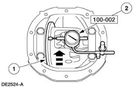
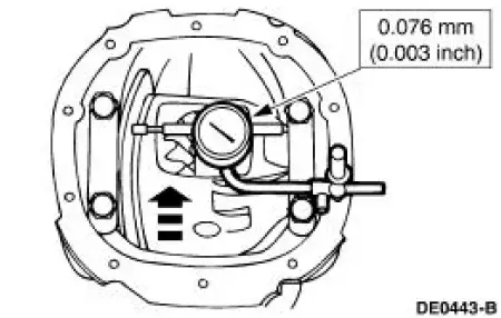
13. Measure and note the differential case runout.
1. Rotate the differential case.
2. Note the runout.
- If the runout does not exceed the specification, install a new ring gear and drive pinion gear. For additional information, refer to Drive Pinion in this section and to Installation in this procedure.
- If the runout exceeds the specification, the ring gear is true and the concern is due to either differential case/differential bearing damage. Proceed as follows.
14. Remove the differential assembly from the differential housing.
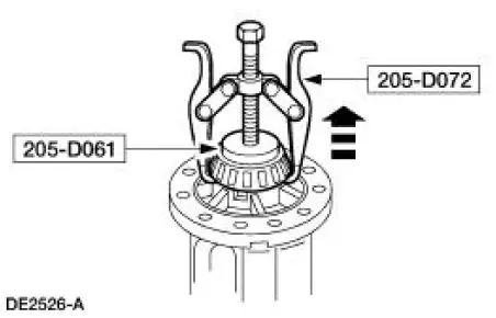
15. Using the special tools, remove the differential bearings.
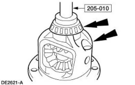
16. Using the special tool, install the new differential bearings.
17. Position the differential assembly, including the differential bearing cups and differential bearing shims, in the differential housing. Install the bearing caps and bolts.
18. Position the special tool.
1. Rotate the differential case to verify that the differential bearings have seated correctly.
2. Position the special tool.
19. Measure the differential case runout.
- If the runout does not exceed the specification, use the new differential bearings for assembly.
- If the runout exceeds the specification, install a new differential case. For additional information, refer to Differential Case and Ring Gear-Conventional or Differential Case and Ring Gear-Traction-Lok in this section.
20. Remove the differential assembly from the differential housing.
 Differential Case
Special Tool(s)
2-Jaw Puller
205-D072 (D97L-4221-A) or
equivalent
Dial Indicator Gauge with
Holding Fixture
100-002 (TOOL-4201-C) or
equivalent
Gauge, Clutch Hou ...
 Installation
All axles
1. Position the ring gear and the differential case. Align the bolt holes by
starting two bolts through
the holes in the differential case and the ring gear. Press the ring gear on the
dif ...
Other materials:
Air Conditioning (A/C) System Flushing
Special Tool(s)
A/C Flush and Purge Machine
219-00022 (part of 219-00023)
or equivalent
A/C Flush and Purge Fitting Kit
219-00024 (part of 219-00023)
or equivalent
WARNING: Use extreme care and observe all safety and service
...
Runout Check - Brake Disc and Hub
Special Tool(s)
Brake Measurement Kit
134-R0199 or equivalent
Material
Item
Specification
High Temperature Nickel Anti-
Seize Lubricant
F6AZ-9L494-AA
ESE-M12A4-
A
CAUTION: The brake disc (1126) runout specification must ...
Engine (Assembly)
Special Tool(s)
Guides, Connecting Rod
303-442 (T93P-6136-A)
Installer, Crankshaft Vibration
Damper
303-102 (T74P-6316-B)
Installer, Front Cover Oil Seal
303-335 (T88T-6701-A)
Installer, Crankshaft Rear ...
