Ford Mustang (1999-2004) Service Manual: Runout Check - Brake Disc and Hub
Special Tool(s)
|
|
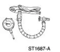
Brake Measurement Kit 134-R0199 or equivalent |
Material
| Item | Specification |
| High Temperature Nickel Anti- Seize Lubricant F6AZ-9L494-AA | ESE-M12A4- A |
CAUTION: The brake disc (1126) runout specification must be met to ensure correct brake performance without roughness complaints.
CAUTION: Do not install brake discs that are less than the minimum thickness specified.
Do not machine a brake disc below the minimum thickness specification.
NOTE: When installing brake discs, always align the painted match marks on the brake discs with those on the front hub or rear axle.
NOTE: When installing brake discs, always apply anti-seize lubricant to the brake disc-to-front hub or to the brake disc-to-rear axle mating surfaces.
1. Do not remove the tire and wheel assembly. Tighten the wheel nuts to specification with a torque stick or torque wrench.
2. Raise and support the vehicle.
3. Assemble the Brake Measurement Kit, using the spherical tip extension.
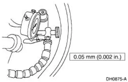
4. Locate an opening on the inboard side of the dust shield that will allow the dial indicator tip to be positioned at least 5 mm (0.2 inch) from the outer edge of the brake disc.
5. NOTE: Do not clamp the gauge set to a vehicle component separated from the brake disc by a flexible joint, such as a ball joint or body mount.
Clamp the Brake Measurement Kit on the vehicle, making sure the flexible indicator arm and probe tip do not touch the dust shield or tire while rotating.
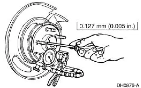
6. NOTE: For rear wheel measurement only, have an assistant push in on the wheel cover or axle shaft center while rotating the wheel.
Rotate the wheel for six revolutions, and record the total indicated runout.
7. If the total indicated runout exceeds the maximum specification, remove the brake disc.
8. Clean the brake disc mounting face of dirt, rust and foreign material.
9. For front wheels, measure and record the total indicated runout of the hub face outside the stud circle.
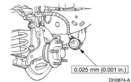
10. Install a new front hub if the total indicated runout exceeds the maximum specification.
- Repeat the hub runout measurement.
11. NOTE: Clean the axle flange surface before measuring.
NOTE: For rear wheels, press inward on the axle shaft while measuring the rear axle runout.
For rear wheels, measure and record the total indicated runout at a point on the axle shaft outside the stud circle.
12. If the total indicated runout exceeds the maximum specification, inspect the rear axle.
- Repeat the rear brake disc runout measurement.
13. If the brake disc TIR is still out of specification, measure and record the thickness of the brake disc. If thickness is sufficient to machine the brake disc to the runout specification, go to Step 14. If the thickness is not sufficient, install a new brake disc and recheck the TIR.
14. NOTE: Brake disc machining must be done with an on-vehicle lathe. Follow the lathe manufacturer's instructions.
Machine the brake disc if final thickness will not be less than the maximum specification.
Recheck the brake disc runout.
 Pressure
1. Clean all dirt from and remove the brake master cylinder filler
cap and fill the brake master
cylinder reservoir with the specified brake fluid.
2. NOTE: Master cylinder pressure bleeder ada ...
 Front Disc Brake
General Specifications
Torque Specifications
...
Other materials:
Wheel Hub or Axle Flange Bolt Circle Runout
NOTE: The brake discs must be removed to carry out all runout
measurements.
1. Position the special tool perpendicular to the wheel hub or axle flange bolt,
as close to the hub
or flange face as possible. Zero the indicator to allow the pointer to deflect
...
Column
Removal and Installation
All vehicles
1. Disconnect the battery ground cable and wait at least one minute to allow
the depletion of the
restraint system backup power supply.
2. WARNING: To avoid the risk of serious personal injury, follow all
warnings,
c ...
Vacuum Hose Repair - Mini-Tube
Special Tool(s)
Vacuum Pump Kit
416-D002 (D95L-7559-A) or
equivalent
1. Measure the length of the damaged area of the mini-tube vacuum hose.
2. Cut a piece of standard 1/8 inch inner diameter vacuum hose approximately 25
mm (1 inch
longer t ...
