Ford Mustang (1999-2004) Service Manual: Removal
1. Remove brake master cylinder filler cap (2162). Check brake fluid level in brake master cylinder reservoir (2K478). Remove fluid until brake master cylinder reservoir is half full.
2. Raise and support the vehicle.
3. Remove the wheel and tire assembly. .
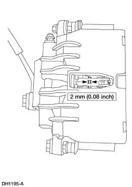
4. CAUTION: Install new pads if worn to or past the specified thickness above the metal backing plate or rivets. Install pads in complete axle sets.
Inspect the pads for wear and contamination.
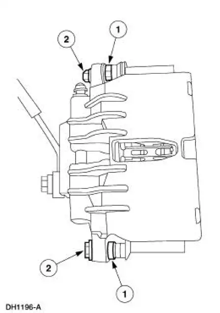
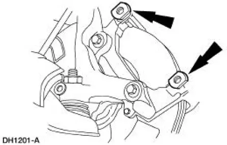
5. Remove the caliper bolts.
1. Hold the guide pins stationary.
2. Remove and discard the caliper bolts.
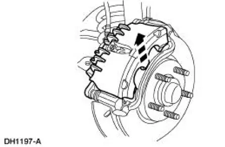
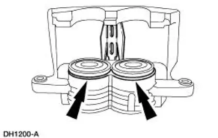
6. CAUTION: Do not pry in caliper sight hole to retract pistons as this can damage the pistons and boots.
CAUTION: When removing the disc brake caliper (2B120), never allow it to hang from the brake hose. Provide a suitable support.
Lift the caliper off the anchor plate (2B292).
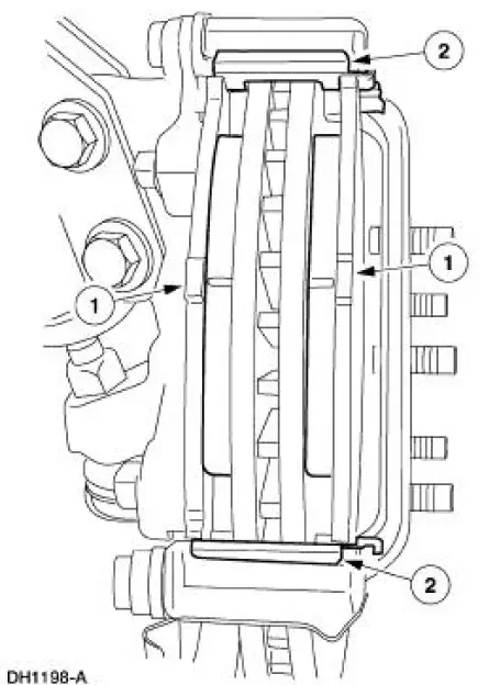
7. Remove the pads and the pad slippers.
1. Remove the pads and verify thickness.
2. Remove and discard slippers.
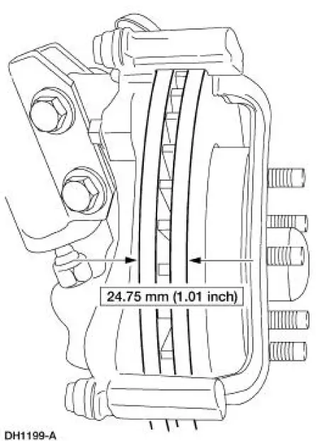
8. Measure the front brake disc thickness.
- Install a new front brake disc (1125) if not within specification.
9. Inspect the disc brake caliper.
- If leaks or damaged boots are found, disassembly is required. For additional information, refer to Caliper in this section.
10. Inspect the front disc brake anchor plate assembly.
- Check the guide pin boots for damage.
- Check the guide pins for binding and damage.
- Worn or damaged pins should be installed new.
 Pads
Pads
...
 Installation
1. CAUTION: Do not allow grease, oil, brake fluid or other
contaminants to contact the
pad lining material. Do not install contaminated pads.
NOTE: Install all hardware supplied with pad kits. ...
Other materials:
Status bars
The top status bar shows the
current mode, exterior temperature,
time and display icons if you have
enabled Bluetooth or other options.
The bottom status bar shows the
Home icon and may show the
current driver and passenger
selected temperatures, fan speed a ...
Stability Control
PRINCIPLES OF OPERATION
WARNING: Vehicle modifications involving braking system,
aftermarket roof racks, suspension, steering system, tire
construction and wheel or tire size may change the handling
characteristics of your vehicle and may adversely affect the ...
Pinpoint Test N: DTC B1869 - Air Bag Indicator Inoperative
Normal Operation
The air bag indicator is designed to illuminate for 6 (+/-2) seconds when
the ignition switch is turned to
the RUN position. This initial 6 seconds of illumination is considered
normal operation and is called
proveout of the air bag ind ...
