Ford Mustang (1999-2004) Service Manual: Removal
1. Disconnect the battery ground cable. For additional information, refer to Section.
2. Remove the engine air cleaner outlet pipe. For additional information, refer to Section.
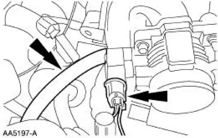
3. Disconnect the vacuum hose and the idle air control (IAC) valve electrical connector.
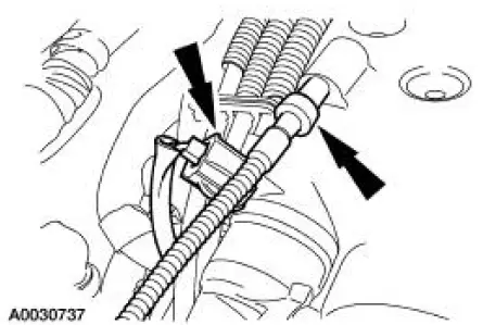
4. Disconnect the throttle position (TP) sensor electrical connector and the evaporative emissions (EVAP) return tube.
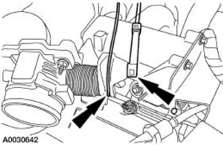
5. Disconnect the accelerator and the speed control cables from the throttle body cam.
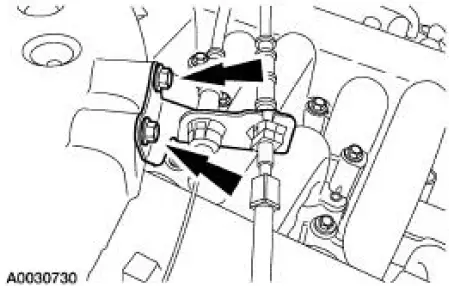
6. Remove the bolts and position the accelerator cable bracket assembly aside.
7. Disconnect the differential pressure feedback exhaust gas recirculation (EGR) system electrical and vacuum connections.
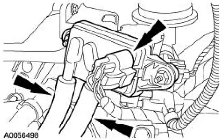
8. Disconnect the EGR vacuum regulator solenoid electrical and vacuum connections.
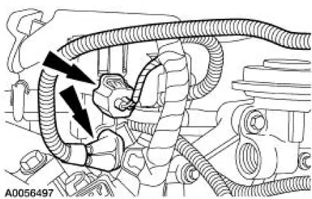
9. Disconnect the positive crankcase ventilation (PCV) tube.
10. Disconnect the vacuum hoses.
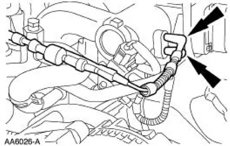
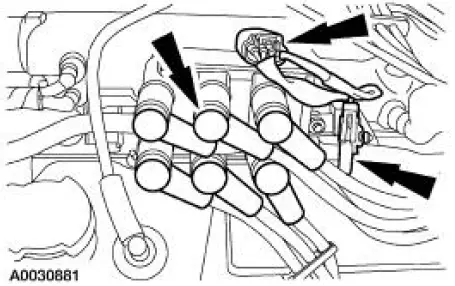
11. Disconnect the following:
- Ignition coil electrical connector.
- Radio interference capacitor electrical connector.
- Spark plug wires.
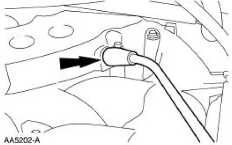
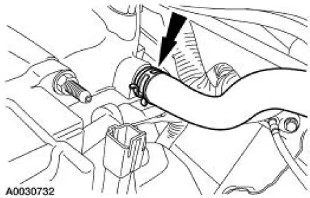
12. Disconnect the vacuum hose.
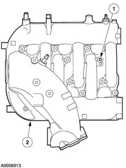
13. NOTE: For ease in installation, record the location of the long bolts and the short bolts.
Remove the upper intake manifold.
1. Remove the 12 bolts.
2. Remove the upper intake manifold.
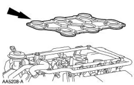
14. Remove and discard the upper intake manifold gasket.

 Installation
1. Install a new upper intake manifold gasket.
2. NOTE: Refer to the location note made during removal and make sure
the bolts are installed in
the correct locations.
Install the upper intake mani ...
Other materials:
General information
WARNING: Extended idling at high engine speeds can produce
very high temperatures in the engine and exhaust system,
creating the risk of fire or other damage.
WARNING: Do not park, idle, or drive your vehicle on dry grass
or other dry ground cover. The emissio ...
Windshield wipers
Note: Fully defrost the windshield before switching on the windshield
wipers.
Note: Make sure you switch off the windshield wipers before entering a
car wash.
Note: Clean the windshield and wiper blades if they begin to leave
streaks or smears. If that does ...
Component Test
Carry out the appropriate Functional Test(s) as determined in Inspection and
Verification.
Functional Test I (Buckle and Tongue)
The safety belt buckle and tongue assembly must operate freely during the
latching and unlatching
function. Fasten the safety bel ...
