Ford Mustang (1999-2004) Service Manual: Installation
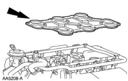
1. Install a new upper intake manifold gasket.
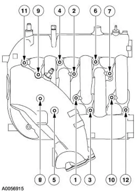
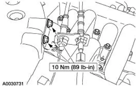
2. NOTE: Refer to the location note made during removal and make sure the bolts are installed in the correct locations.
Install the upper intake manifold. Tighten the bolts in two stages in the sequence shown.
- Stage 1: Tighten to 10 Nm (89 lb-in).
- Stage 2: Rotate an additional 90 degrees (1/4 turn).
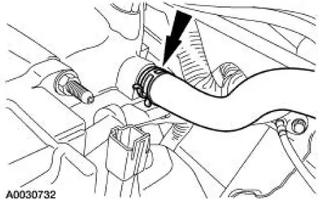
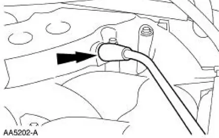
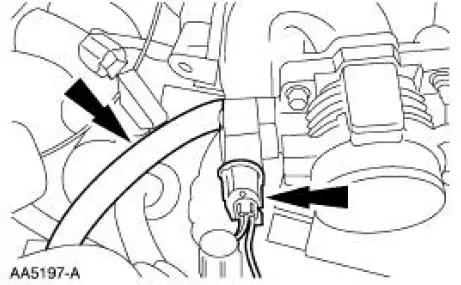
3. Connect the vacuum hose.
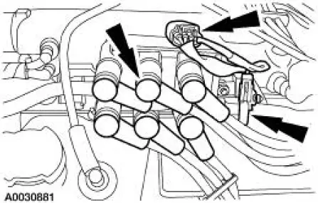
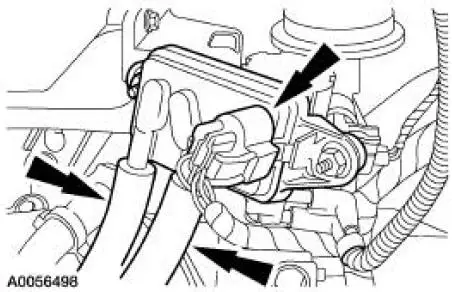
4. Connect the following:
- Ignition coil electrical connector.
- Radio interference capacitor electrical connector.
- Spark plug wires.
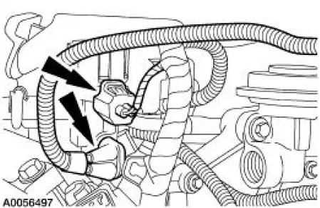
5. Connect the vacuum hoses.
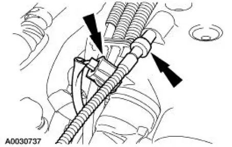
6. Connect the PCV tube.
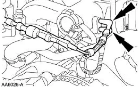
7. Connect the differential pressure feedback EGR system electrical and vacuum connections.
8. Connect the EGR vacuum regulator solenoid electrical and vacuum connections.
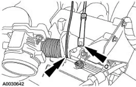
9. Position the accelerator cable bracket and install the bolts.
10. Connect the accelerator and speed control cables to the throttle body cam.
11. Connect the EVAP return tube and the TP sensor electrical connector.
12. Connect the vacuum hose and the IAC valve electrical connector.
13. Install the engine air cleaner outlet pipe. For additional information, refer to Section .
14. Connect the battery ground cable. For additional information, refer to Section .
 Removal
1. Disconnect the battery ground cable. For additional information, refer
to Section.
2. Remove the engine air cleaner outlet pipe. For additional information,
refer to Section.
3. Disconnect ...
 Lower Intake Manifold
Material
...
Other materials:
Pinpoint Tests
PINPOINT TEST P1464: DTC P1464: A/C DEMAND OUT OF SELFTEST
RANGE
Test Step
Result / Action to Take
P14641 RECHECK FOR THE DTC
YesGO to P14642 .
No
The system is functioning
correctly. This DTC will set if the
A/C is turned on when carryi ...
Differential Case and Ring Gear - Conventional
Special Tool(s)
2-Jaw Puller
205-D072 (D97L-4221-A) or
equivalent
Installer, Differential Side
Bearing
205-010 (T57L-4221-A2)
Step Plate
205-D061 (D83T-4205-C2) or
equivalent
...
Assembly
1. Install the new O-ring.
2. Assemble the gear shifter forks.
1. Install the gear shift plate into the gear shifter fork.
2. Install the gear shift fork inserts.
3. NOTE: Position the narrow side of the C-shaped gear selector
interlock sleeve in ...
