Ford Mustang (1999-2004) Service Manual: Removal
1. Remove the air intake scoop bracket. For additonal information, refer to Section.
2. Remove the air cleaner outlet tube. For additional information, refer to Section.
3. Disconnect the accelerator cable, the speed control actuator cable and the return spring.
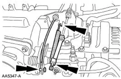
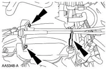
4. Remove the bolts, disconnect the clip and position the cables out of the way.
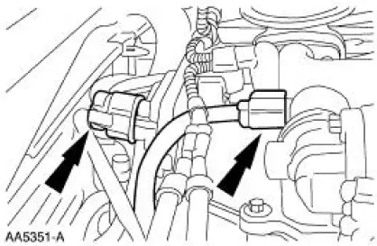
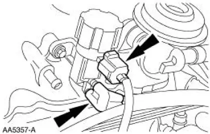
5. Disconnect the throttle position (TP) sensor.
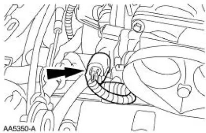
6. Disconnect the evaporative emissions (EVAP) return hose.
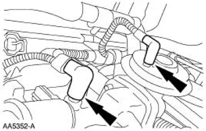
7. Disconnect the idle air control valve and the differential pressure feedback EGR.
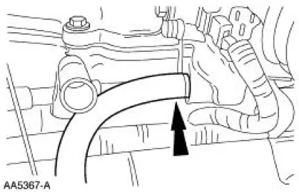
8. Disconnect the main chassis vacuum supply line and the EGR valve vacuum line.
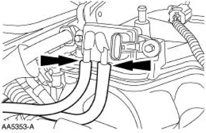
9. Disconnect the differential pressure feedback EGR hoses.
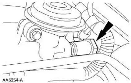
10. Disconnect the EGR valve to exhaust manifold tube from the EGR valve.
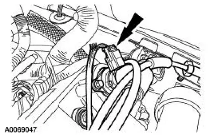
11. Disconnect the electrical connector and the vacuum lines from the EGR vacuum regulator solenoid.
12. Remove the PCV valve-to-intake manifold tube.
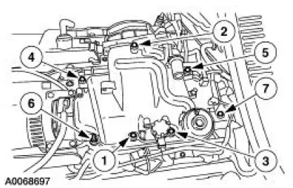
13. Remove the upper intake manifold bolts in the sequence shown and remove the intake manifold assembly.
14. Inspect and clean the sealing surfaces.

 Installation
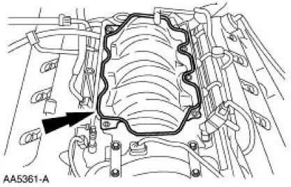
1. Install the upper intake manifold gasket.
2. Install the intake manifold and bolts in the sequence shown.
3. Install the PCV valve-to-intake manifold tube.
4. Connect the vacuum hoses and ...
Other materials:
Lock Cylinder - Luggage Compartment Lid
Removal
1. NOTE: Individual lock cylinders are repaired by discarding the
inoperative cylinder and building
a new lock cylinder using the appropriate lock repair package. The lock
repair package includes
a detailed instruction sheet to build the ne ...
Brake Booster - Hydro-Boost (Removal and Installation)
Special Tool(s)
Installer Set, Teflon Seal
211-D027 (D90P-3517-A) or
equivalent
Removal
WARNING: The power brake booster should not be carried by the
accumulator, nor
should it ever be dropped on the accumulator. Check the snap ring on th ...
Disassembly
1. Remove the driveshaft (4602). For additional information, refer to
Driveshaft in this section.
2. CAUTION: Under no circumstances is the driveshaft assembly to be
clamped in the
jaws of a vise or similar holding fixture. Denting or localizing fracture ca ...
