Ford Mustang (1999-2004) Service Manual: Disassembly
1. Remove the driveshaft (4602). For additional information, refer to Driveshaft in this section.
2. CAUTION: Under no circumstances is the driveshaft assembly to be clamped in the jaws of a vise or similar holding fixture. Denting or localizing fracture can result, causing driveshaft failure during vehicle operation.
Place the driveshaft on a suitable workbench, being careful not to damage the tube.
3. NOTE: If components are not marked and installed correctly, driveline imbalance can occur.
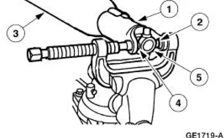
Index-mark the positions of the driveshaft components.
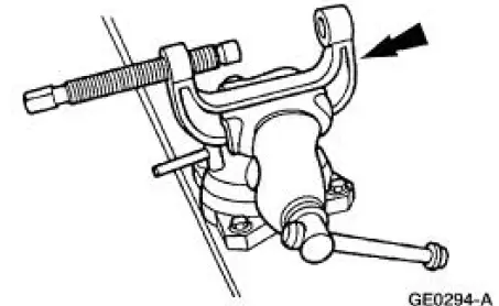
4. Clamp the U-joint tool in a vise.
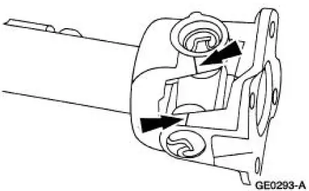
5. Remove all four of the snap rings.
6. Remove the driveshaft flange yoke.
1. Position the driveshaft flange yoke in the U-joint tool.
2. Press out a bearing cup.
3. Remove the driveshaft flange yoke.
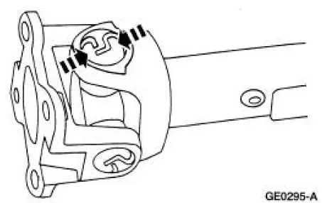
4. Press on the spider to remove the remaining bearing cup.
5. Remove the driveshaft flange yoke.
7. Remove the spider.
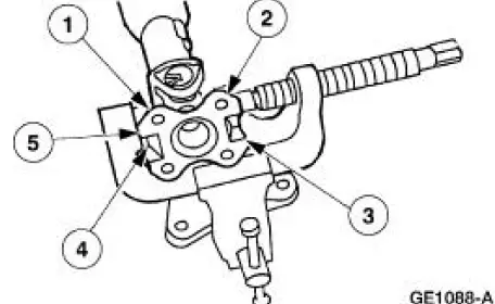
1. Reposition the driveshaft in the U-joint tool.
2. Press out the bearing cup.
3. Rotate the driveshaft.
4. Press on the spider to remove the remaining bearing cup.
5. Remove the spider.
8. Clean the yoke area at the end of the driveshaft.
 Universal Joint - Single Cardan, Flange Yoke
Special Tool(s)
Installer/Remover, C Frame
and Screw
205-086 (T74P-4635-C)
...
 Assembly
1. NOTE: Universal joint kits are to be installed as complete
assemblies only. Do not mix
components from other U-joint kits.
Install the spider.
1. Start a new bearing cup into the driveshaft yok ...
Other materials:
Exhaust Manifold RH
Special Tool(s)
Lifting Bracket, Engine
303-D088 (D93P-6001-A2)
Support Bar, Engine
303-290-A
Removal and Installation
1. Install the special tool.
2. Install the special tools.
3. Raise and support the vehicle. For additional ...
Retractor - Rear Seat Safety Belt, Convertible
Special Tool(s)
Torx Bit, Safety Belt Bolt
501-010 (T77L-2100-A)
Removal
1. Remove the rear seat cushion.
2. Remove the luggage compartment front lining board (45444).
3. Release the safety belt guide.
4. Using the special tool, remove the ...
Engine Support Insulators
Special Tool(s)
3 Bar Engine Support Kit
303-F072
Engine Lift Bracket Set
303-D095 (D94L-6001-A) or
equivalent
...
