Ford Mustang (1999-2004) Service Manual: Removal
1. Disconnect the battery ground cable. For additional information, refer to Section.
2. Drain the cooling system. For additional information, refer to Section.
3. Recover the refrigerant. For additional information, refer to Section.
4. Remove the air cleaner outlet tube. For additional information, refer to Section.
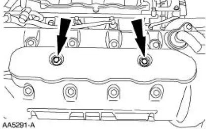
5. Remove the RH ignition coil cover bolts and the cover.
6. Disconnect the ignition coil electrical connectors.
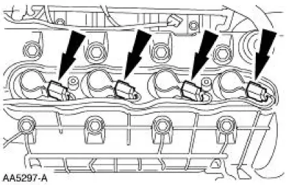
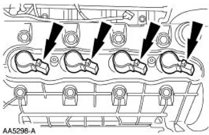
7. Remove the ignition coils.
8. Remove the throttle body. For additional information, refer to Section.
9. Disconnect the fuel tube spring lock coupling. For additional information, refer to Section.
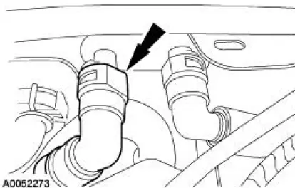
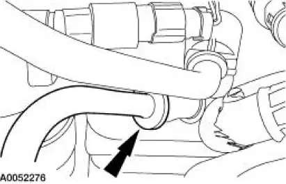
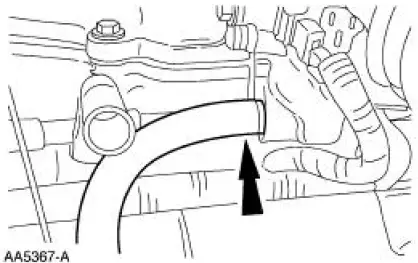
10. Disconnect the heater hose.
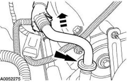
11. Disconnect the A/C suction tube at the accumulator.
12. Disconnect and remove the A/C suction tube.
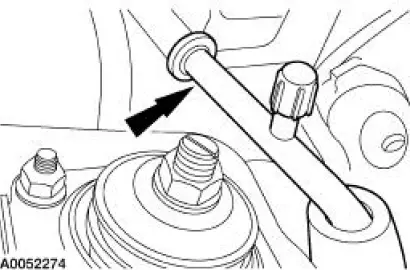
13. Remove the nut and separate the A/C tube from the condenser.
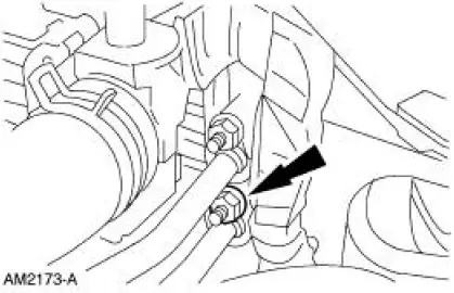
14. Disconnect the A/C tube at the evaporator.
15. Remove the A/C tube.
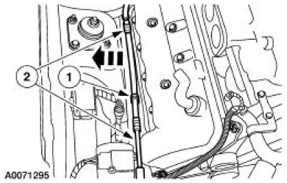
1. Disconnect the pin-type retainer.
2. Remove the A/C tube.
16. Disconnect the evaporative emissions (EVAP) return tube.
17. Disconnect the wiring harness from the valve cover stud bolt.
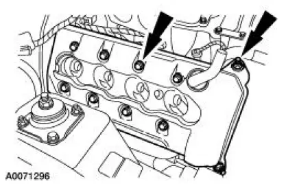
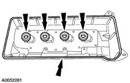
18. Remove the bolts and the RH valve cover.
19. CAUTION: Do not use metal scrapers, wire brushes, power abrasive discs or other abrasive means to clean the sealing surfaces. These tools cause scratches and gouges which make leak paths. Use a plastic scraping tool to remove all traces of old sealant.
Clean and inspect the sealing surfaces and inspect the valve cover gaskets. If necessary, install new gaskets. Make sure the gaskets are correctly seated on the valve cover.
 Valve Cover RH
Material
Item
Specification
Metal Surface Cleaner
F4AZ-19A536-RA or equivalent
WSE-M5B392-
A
Silicone Gasket and Sealant
F7AZ-19554-EA or equivalent
WSE-M4G323-
A4
...
 Installation
1. NOTE: If the valve cover is not secured within four minutes, the sealant
must be removed and
the sealing area cleaned with metal surface cleaner. Allow to dry until there is
no sign of
wetness, o ...
Other materials:
Removal
WARNING: Always wear safety glasses when repairing an air bag
supplemental restraint
system (SRS) vehicle and when handling an air bag module. This will
reduce the risk of injury
in the event of an accidental deployment.
WARNING: Carry a live air ...
Throttle Body
Removal and Installation
WARNING: Do not smoke or carry lighted tobacco or open flame of any
type when
working on or near any fuel related components. Highly flammable mixtures are
always present
and can ignite. Failure to follow these instructions can resul ...
Pulley - CIII Pump
Special Tool(s)
Pump Pulley Replacer
211-185 (T91P-3A733-A)
Pump Pulley Remover
211-016 (T69L-10300-B)
Removal
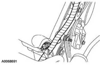
1. Remove the drive belt.
2. Raise and support the vehicle.
3. Using the special tool, remove the pulley.
Inspect the p ...
