Ford Mustang (1999-2004) Service Manual: Removal
All vehicles
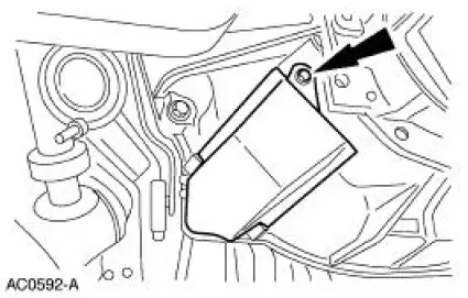
1. Remove the air intake scoop. For additional information, refer to Section.
2. Remove the Hydro-Boost brake booster. For additional information, refer to Section..
3. Raise and support the vehicle. For additional information, refer to Section.
Manual transmission vehicles
4. Remove the screw and the dust shield.
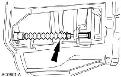
5. Disengage the clutch release cable from the clutch release fork.
6. Lower the vehicle.
7. Remove the two screws and position the clutch release cable aside.
All vehicles
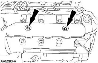
8. Remove the LH ignition coil cover bolts and the cover.
9. Disconnect the ignition coil electrical connectors.
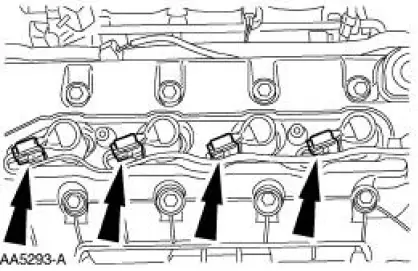
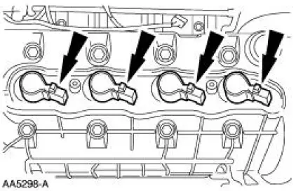
10. Remove the ignition coils
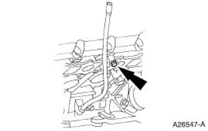
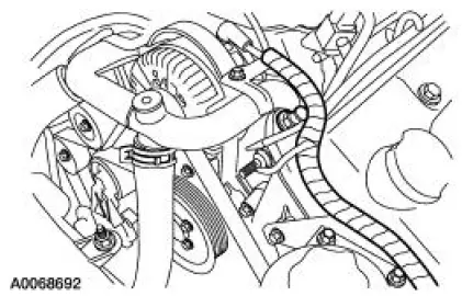
11. Remove the bolt and position the oil level indicator tube aside.
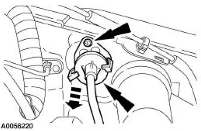
12. Disconnect the positive crankcase ventilation (PCV) valve hose and the electrical connector.
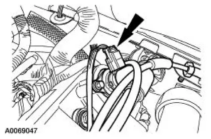
13. Disconnect the wiring harness anchor from the valve cover.
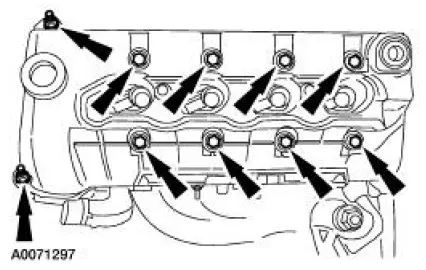
14. Remove the LH valve cover.
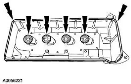
15. CAUTION: Do not use metal scrapers, wire brushes, power abrasive discs or other abrasive means to clean the sealing surfaces. These tools cause scratches and gouges which make leak paths. Use a plastic scraping tool to remove all traces of old sealant.
Clean and inspect the sealing surfaces and the valve cover gaskets. If necessary, install new gaskets. Make sure the gaskets are correctly seated on the valve cover.
 Valve Cover LH
Material
Item
Specification
Metal Surface Cleaner
F4AZ-19A536-RA or
equivalent
WSE-M5B392-A
Silicone Gasket and Sealant
F7AZ-19554-EA or equivalent
WSE-M4G323-
A4
...
 Installation
All vehicles
1. NOTE: If the valve cover is not secured within four minutes, the sealant
must be removed and
the sealing area cleaned with metal surface cleaner. Allow to dry until there is
no sign ...
Other materials:
Piston - Selection
NOTE: The cylinder bore must be within the specifications for
taper and out-of-round before fitting a
piston.
1. Select a piston size based on the cylinder bore.
2. NOTE: For precision fit, new pistons are divided into three
categories within each size ...
Toe Adjustment - Rear
1. Loosen the nuts.
To prevent damage to the ball joints, hold the tie-rod ends while
loosening the nuts.
2. Rotate the toe link to the correct toe setting.
3. Tighten the nuts.
To prevent damage to the ball joints, hold the tie-rod ends wh ...
Engine Cooling (Diagnosis and Testing)
Special Tool(s)
Pressure Tester
014-R1072 or equivalent
73III Automotive Meter
105-R0057 or equivalent
Worldwide Diagnostic System
(WDS)
418-F224,
New Generation STAR (NGS)
Tester
418-F052, or equivalent scan ...
