Ford Mustang (1999-2004) Service Manual: Installation
All vehicles
1. NOTE: If the valve cover is not secured within four minutes, the sealant must be removed and the sealing area cleaned with metal surface cleaner. Allow to dry until there is no sign of wetness, or four minutes, whichever is longer. Failure to follow this procedure can result in future oil leakage.
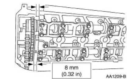
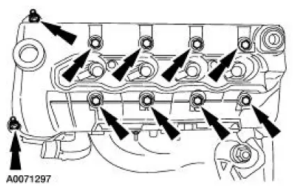
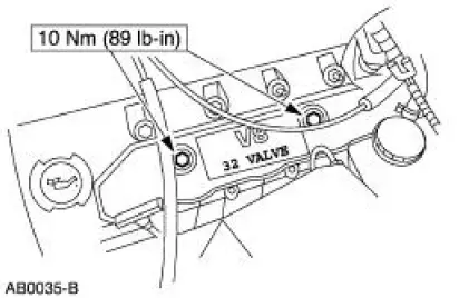
Apply silicone gasket and sealant to areas shown.
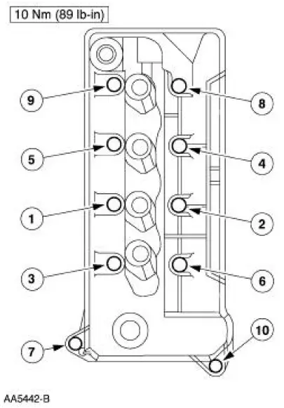
2. Install the LH valve cover and loosely install the bolts.
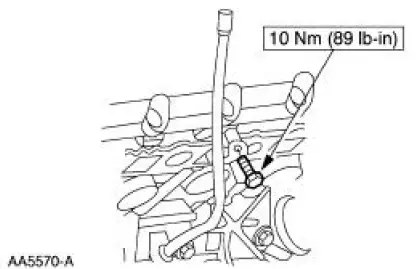
3. Tighten the LH valve cover bolts in the sequence shown.
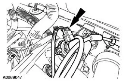
4. Connect the wiring harness anchor to the valve cover stud bolt.
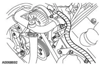
5. Connect the positive crankcase ventilation (PCV) valve hose and electrical connector.
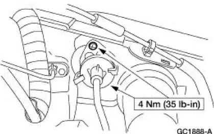
6. Position the oil level indicator tube and install the bolt.
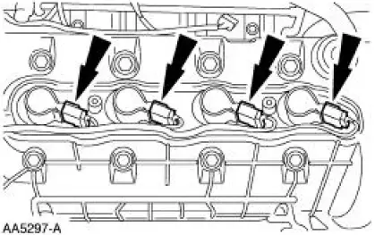
7. Install the LH ignition coils.
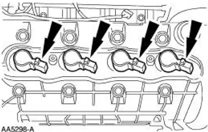
8. Connect the ignition coil electrical connectors.
9. Install the LH ignition coil cover and the bolts.
Manual transmission vehicles
10. Install the clutch release cable and install the two screws.
11. Raise and support the vehicle. For additional information, refer to Section.
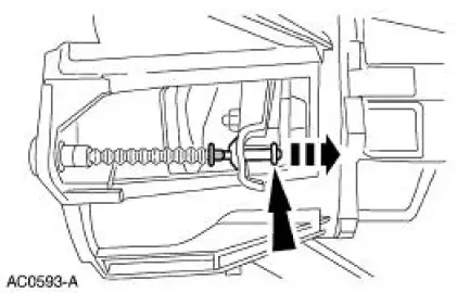
12. Connect the clutch release cable to the clutch release fork.
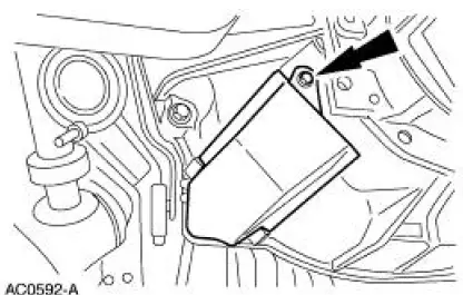
13. Install the dust shield and the screw.
14. Lower the vehicle.
All vehicles
15. Install the Hydro-Boost brake booster. For additional information, refer to Section.
16. Install the air intake scoop. For additional information, refer to Section.
 Removal
All vehicles
1. Remove the air intake scoop. For additional information, refer to Section.
2. Remove the Hydro-Boost brake booster. For additional information, refer to
Section..
3. Raise and suppo ...
Other materials:
Parking Brake Cable Tension Release
1. CAUTION: If any component in the parking brake system requires
repair or if the
rear axle housing (4010) is removed, the cable tension must be released.
Place the parking brake control (2780) in the released position.
2. Remove the console.
3. W ...
Component Tests
Ball Joint Inspection
1. Raise and support the vehicle.
2. Prior to performing any inspection of the ball joints, inspect the wheel
bearings.
3. Position a safety stand beneath the front suspension lower arm (3079) to be
tested.
4. While an assistant pul ...
Removal
CAUTION: Suspension fasteners are critical parts because they affect
performance of vital
components and systems and their failure can result in major service expense. A
new part with
the same part number must be installed if installation becomes necessary. ...
