Ford Mustang (1999-2004) Service Manual: Removal
Both mounts
1. Disconnect the battery ground cable. For additional information, refer to Section.
2. Remove the coolant bypass tube. For additional information, refer to Section.
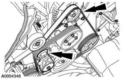
3. Rotate the drive belt tensioner clockwise and detach the drive belt from the generator pulley.
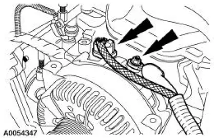
4. Disconnect the generator electrical connections.
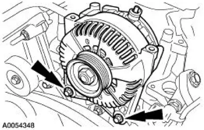
5. Remove the bolts and the generator.
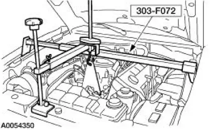
6. Install the special tool.
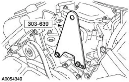
7. Using the special tool, support the engine.
8. Remove the front springs. For additional information, refer to Section.
9. NOTE: RH shown, LH similar.
Remove the six splash-shield pushpins.
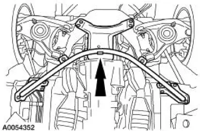
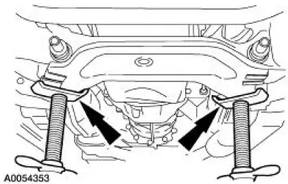
10. Remove the 13 bolts and the cross-brace support.
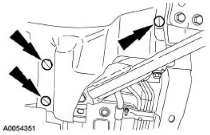
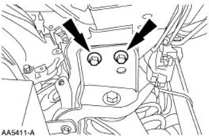
11. NOTE: RH shown, LH similar.
Remove the two engine mount nuts.
12. Using two jackstands, support the subframe.
13. NOTE: Mark the bolts and the crossmember location for assembly reference.
NOTE: RH shown, LH similar.
Remove the four bolts.
14. NOTE: RH shown, LH similar.
Remove the four bolts.
15. Using the jackstands, lower the front subframe.
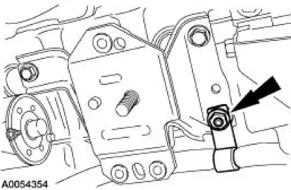
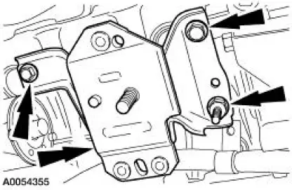
RH mount
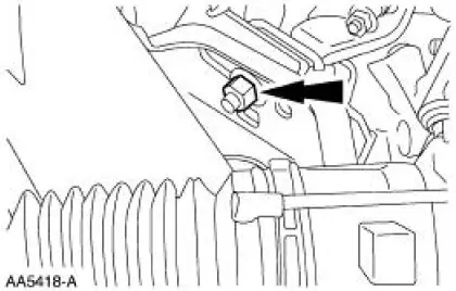
16. Remove the nut and detach the wiring harness.
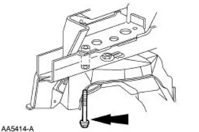
17. Remove the bolts, the studbolt and the engine mount.
LH mount
18. Remove the nuts and detach the ground cables.
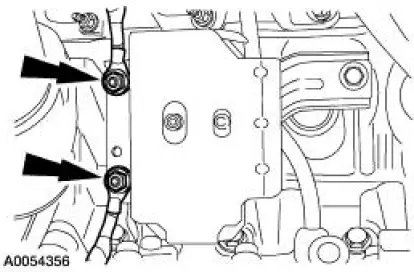
19. Remove the bolt, the studbolts and the engine mount.
 Engine Mount
Special Tool(s)
Support Bracket, Engine
303-639
3-Bar Engine Support Kit
303-F072
Alignment Tool, Subframe
502-004
...
 Installation
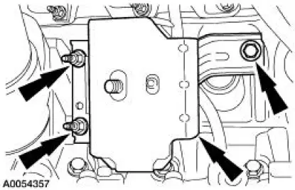
LH mount
1. Position the engine mount and install the bolt and studbolts.
2. Attach the ground cables and install the nuts.
RH mount
3. Position the engine mount and install the bolts and studbolt ...
Other materials:
Exhaust Manifold - LH
Removal
1. Raise and support the vehicle. For additional information, refer to
Section.
2. Remove the LH exhaust manifold flange nuts.
3. Remove the RH exhaust manifold flange nuts.
4. Lower the vehicle.
5. NOTE: Discard the exhaust manifold gasket.
...
Removal
1. Use a suitable suction device to lower the brake fluid level in
the master cylinder reservoir.
2. Raise and support the vehicle.
3. Remove the wheel and tire assembly.
4. Inspect the pads for wear or contamination, install new if worn to ...
Removal
1. Remove the differential assembly from the differential housing. For
additional information, refer
to Differential Case in this section.
2. CAUTION: Record the torque necessary to maintain rotation of the drive
pinion gear
through several revolutions prio ...
