
Ford Mustang (1999-2004) Service Manual: Starting System (Diagnosis and Testing)
Refer to Wiring Diagrams Cell 20 , Starting System for schematic and connector information.
Special Tool(s)
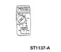 |
Digital Multimeter 105-R0051 or equivalent |
 Starting System (Description and Operation)
Starter Motor
The starter motor is a 12-volt unit that has the starter solenoid mounted on
the drive end housing and
functions as follows:
The current flows through the solenoid energizing coil unt ...
 Inspection and Verification
WARNING: When servicing starter motor or carrying out other underhood
work in the
vicinity of the starter motor, be aware that the heavy gauge battery input lead
at the starter
solenoid is "electric ...
Other materials:
Cable and Bracket
Removal
1. Raise the vehicle on a hoist. For additional information, refer to
Section.
2. Remove the cable shift from the shifter lever and bracket and discard
the clip.
3. Remove the bolt from the cable.
4. Remove the bolt from the cable.
5. ...
Principles of Operation
Key-In-Ignition Warning Chime
The key-in-ignition warning chime activates when the generic
electronic module (GEM) detects the
ignition switch circuits are in the OFF or ACC states and when the GEM
detects the driver door is ajar
from the driver do ...
911 Assistâ„¢
WARNING: Unless the 911 Assist setting is set on prior to a
crash, the system will not dial for help which could delay
response time, potentially increasing the risk of serious injury or death
after a crash.
WARNING: Do not wait for 911 Assist to make an emerg ...
