Ford Mustang (1999-2004) Service Manual: Supply Manifold
Removal
WARNING: Do not smoke or carry lighted tobacco or open flame of any type when working on or near any fuel related components. Highly flammable mixtures are always present and can ignite. Failure to follow these instructions can result in personal injury.
WARNING: Fuel in the fuel system remains under high pressure even when the engine is not running. Before working on or disconnecting any of the fuel lines or fuel system components, the fuel system pressure must be relieved. Failure to follow these instructions can result in personal injury.
1. Disconnect the battery ground cable. For additional information, refer to Section.
2. Remove the upper intake manifold. For additional information, refer to Section.
3. Relieve the fuel pressure. For additional information, refer to Section.
4. Disconnect the fuel line. For additional information, refer to Section.
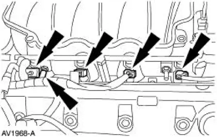
5. Position the wiring harness aside.
- Disconnect the RH fuel injector electrical connectors.
- Separate the harness from the RH fuel supply manifold stud bolt.
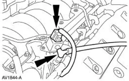
6. Disconnect the fuel pressure sensor.
- Disconnect the electrical connector.
- Disconnect the vacuum hose.
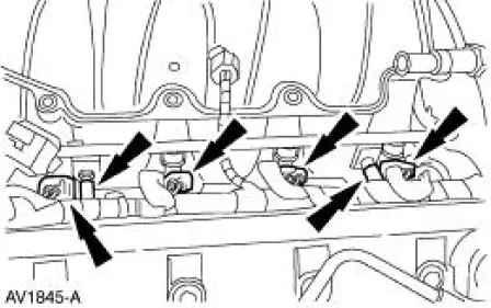
7. Position the wiring harness aside.
- Disconnect the LH fuel injector electrical connectors.
- Separate the harness from the LH fuel supply manifold stud bolt.
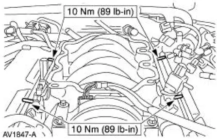
8. Remove the fuel supply manifold.
- Remove the four bolts.
Installation
1. NOTE: When the battery is disconnected and reconnected, some abnormal drive symptoms may occur while the vehicle relearns its adaptive strategy. The vehicle may need to be driven 16 km (10 mi) or more to relearn the strategy.
To install, reverse the removal procedure.
 Installation
1. Position the wiring harness:
Install the wiring harness retainer onto the LH valve cover stud bolt.
Install the wiring harness retainer into the power steering reservoir.
2. Connect the EC ...
 Accessory Drive
General Specifications
Item
Specification
Accessory drive belt
6 ribs
Supercharger drive belt
8 ribs
Torque Specifications
...
Other materials:
Spark Plugs
Removal and Installation
1. Remove the ignition coil-on-plug. For additional information, refer to
Ignition Coil-On-Plug in this
section.
2. NOTE: Use compressed air to remove any foreign material from the
spark plug well before
removing the spark plu ...
Assembly
1. Lubricate the differential side gear thrust washers and the differential
side gear journals, and
assemble the washers to the gears.
Use SAE 75W-140 High Performance Rear Axle Lubricant F1TZ-19580-B or
equivalent
meeting Ford specification WSL-M2C192-A ...
Waxing
Regular waxing is necessary to protect the paint on your car from the
elements. We recommend that you wash and wax the painted surface
once or twice a year.
When washing and waxing, park your vehicle in a shaded area out of
direct sunlight. Always wash your v ...
