Ford Mustang (1999-2004) Service Manual: Communications Network (Diagnosis and Testing)
Refer to Wiring Diagrams Cell 14 , Multiplex Communication Network for schematic and connector information.
Special Tool(s)
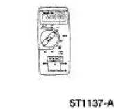 |
73 Digital Multimeter or equivalent 105-R0051 |
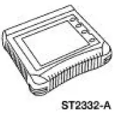 |
Worldwide Diagnostic System (WDS) 418-F224, New Generation STAR (NGS) Tester 418-F052, or equivalent diagnostic tool |
 Module Communications Network
General Specifications
Communications Network
Module Communications Network
...
 Principles of Operation
The vehicle has two module communications networks. The standard
corporate protocol (SCP) which
is an unshielded twisted pair cable (data bus plus, Circuit 914 [TN/OG] and
data bus minus, Circuit ...
Other materials:
Installation
NOTE: Do not use a fiber disc to clean the surfaces. Fibers from
the disc can get into the oil pan and
oil and clog the oil bypass valve.
1. Clean and inspect the cylinder head for flatness.
2. Install a new head gasket on the cylinder block with the sma ...
Muffler - 4.6L (2V)
Removal and Installation
1. Use a jack to support and lower the rear axle.
2. Remove the upper arm-to-differential bolt.
3. Remove the nut and bolt, and disconnect the rear shock absorbers (18124)
from the axle
housing.
Discard the nut.
4. Lower the r ...
Dual-Function Pressure Switch (4.6L)
The dual-function pressure switch is used to interrupt A/C compressor
operation in the event of high system discharge pressures.
The dual-function pressure switch is mounted on a Schrader valve-type
fitting on the high
pressure side of the A/C manifold ...
