Ford Mustang (1999-2004) Service Manual: Evaporative Emission Canister
Removal and Installation
1. WARNING: The evaporative emission system contains fuel vapor and condensed fuel vapor. Although not in large quantities, it still presents the danger of explosion or fire. Disconnect the battery ground cable from the battery to minimize the possibility of an electrical spark occurring, possibly causing a fire or explosion if fuel vapor or liquid fuel is present in the area. Failure to follow these instructions may result in personal injury.
Disconnect the battery ground cable. For additional information, refer to Section.
2. Raise and support the vehicle. For additional information, refer to Section.
3. Remove the left rear wheel. For additional information, refer to Section.
4. WARNING: Do not smoke or carry lighted tobacco or open flame of any type when working on or around any fuel-related component. Highly flammable mixtures are always present and may be ignited. Failure to follow these instructions may result in personal injury.
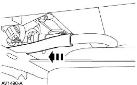
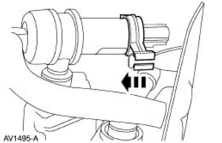
Disconnect the canister vent solenoid hose assembly.
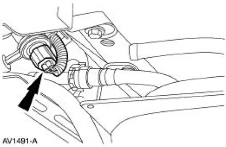
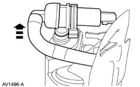
5. Disconnect the connector.
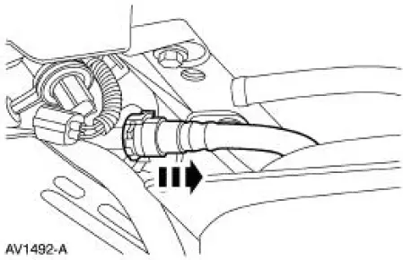
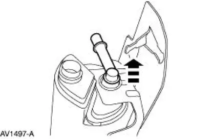
6. Disconnect the evaporative emission (EVAP) canister purge outlet tube.
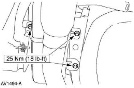
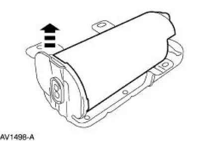
7. Remove the EVAP canister with bracket assembly from the vehicle.
- Remove the bolts.
8. Disconnect the brace.
9. Remove the canister vent solenoid and canister vent solenoid hose assembly
10. Remove the EVAP canister purge outlet tube elbow.
11. Remove the EVAP canister from the canister bracket.
12. To install, reverse the removal procedure.
- Carry out a leak test. For additional information, refer to Evaporative Emission System Leak Test in this section.
- Carry out the evaporative emission repair verification drive cycle. For additional information, refer to Evaporative Emission Repair Verification Drive Cycle in this section.
 Evaporative Emission Repair Verification Drive Cycle
Special Tool(s)
Worldwide Diagnostic System
(WDS)
418-F224,
New Generation STAR (NGS)
Tester
418-F052, or equivalent scan
tool
Drive Cycle Recommendations
NOTE: The followi ...
 Evaporative Emission Canister Purge Valve
Removal and Installation
1. WARNING: The evaporative emission system contains fuel vapor
and condensed
fuel vapor. Although not in large quantities, it still presents the
danger of explosion ...
Other materials:
Transmission Cooling - Integral
This vehicle with an automatic transmission is equipped with an integral
transmission fluid cooler. The
cooler is contained inside of the radiator outlet tank and cannot be serviced
separately. The cooler
transfers heat from the transmission fluid to the eng ...
Mass Air Flow (MAF) Sensor - Cobra
Removal and Installation
1. Disconnect the intake air temperature (IAT) sensor.
2. Disconnect the breather hose.
3. Disconnect the vacuum hose.
4. Loosen the clamps and remove the air cleaner outlet pipe.
5. CAUTION: The mass air flow (MAF) sensor ho ...
Transmission (Disassembly)
Special Tool(s)
Remover, Mainshaft Bearing
308-058 (T77J-7025-H)
Screw, Bearing Removal tube
308-092 (T84T-7025-B)
Holding Fixture, Transmission
307-003 (T57L-500-B)
Remover, Bushing
307-001 (TOOL-1175-AC) ...
