Ford Mustang (1999-2004) Service Manual: Exhaust Manifold LH
Removal and Installation
1. Position the steering wheel straight ahead and lock the column.
2. Disconnect the battery ground cable. For additional information, refer to Section.
3. Raise the vehicle. For additional information, refer to Section.
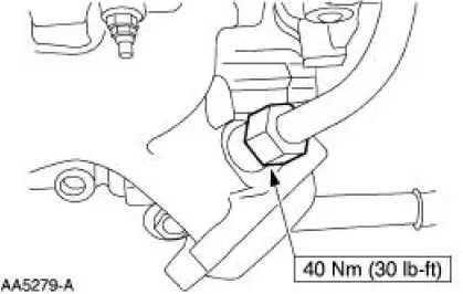
4. Remove the dual converter Y-pipe. For additional information, refer to Section.
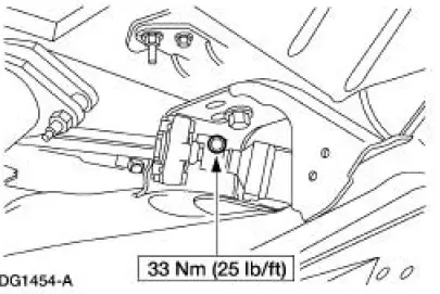
5. Remove and discard the pinch bolt.
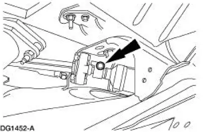
6. Separate the steering coupler.
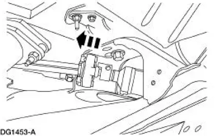
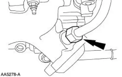
7. Disconnect the exhaust gas recirculation (EGR) tube at the exhaust manifold.
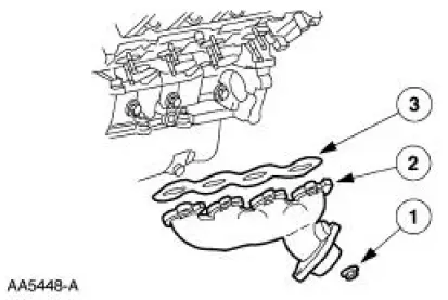
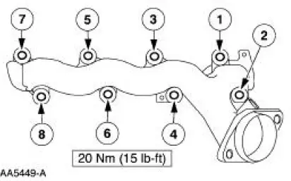
8. Remove the exhaust manifold.
1. Remove the nuts.
2. Remove the exhaust manifold.
3. Remove and discard the gasket.
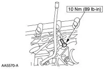
9. Remove the oil level indicator tube.
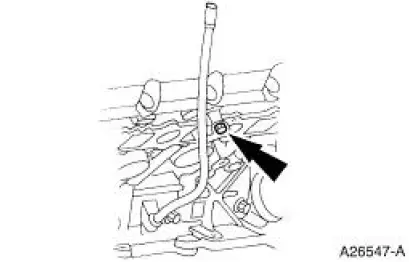
10. Remove and discard the exhaust manifold gasket.
11. To install, reverse the removal procedure.
- Use a new exhaust manifold gasket.
 Exhaust Manifold RH
Removal and Installation
1. Disconnect the battery ground cable. For additional information, refer to
Section.
2. Raise the vehicle. For additional information, refer to Section.
3. Remove the dual ...
 Oil Filter Adapter
Removal
1. Drain the cooling system. For additional information, refer to Section.
2. Disconnect the lower radiator hose.
3. Raise the vehicle. For additional information, refer to Section.
4. Dra ...
Other materials:
Damper
Removal
CAUTION: Suspension fasteners are critical parts because they affect
performance of vital
components and systems and their failure can result in major service expense. A
new part with
the same part number must be installed if installation becomes nec ...
Bumpers
Torque Specifications
Bumpers
CAUTION: Never apply excessive heat to the bumper cover surface. Heat
could cause
distortion of the bumper cover.
The bumper systems consist of the following components:
front bumper
front bumper cover
front bumper cover (Co ...
Subwoofer Amplifier - Convertible
Removal and Installation
1. NOTE: The convertible top needs to be in the up position to
remove the subwoofer amplifiers.
From inside the luggage compartment, remove the forward panel.
1. Remove the pin-type retainers.
2. Remove the forward pa ...
