Ford Mustang (1999-2004) Service Manual: Engine - Mach I 4.6L (4V)
General Specifications
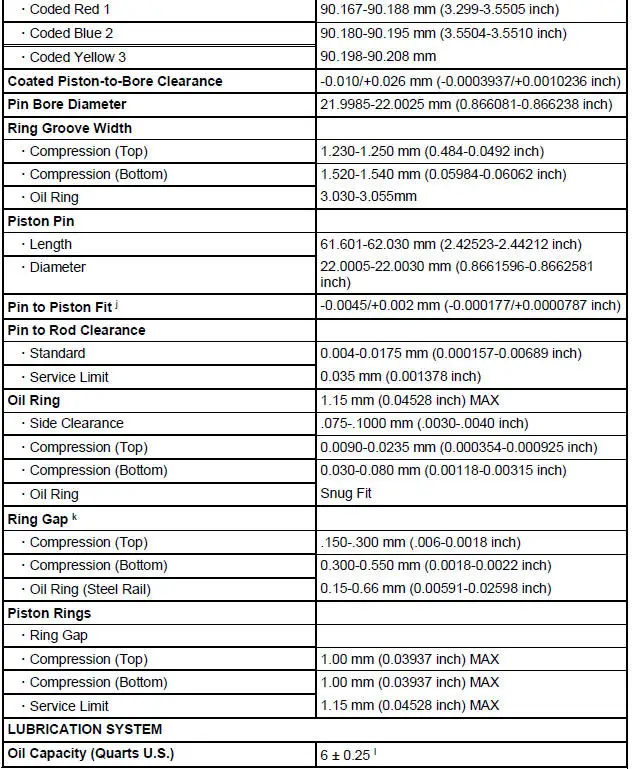
Engine Specifications
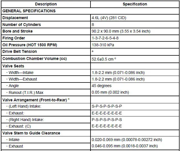
a - Newly Installed-Refers to the condition of the "NEW" drive belt before the engine has made no more than one rotation and before the belt has had a chance to stretch or seat into the pulley grooves.
c - P=Primary, S=Secondary, E=Exhaust.
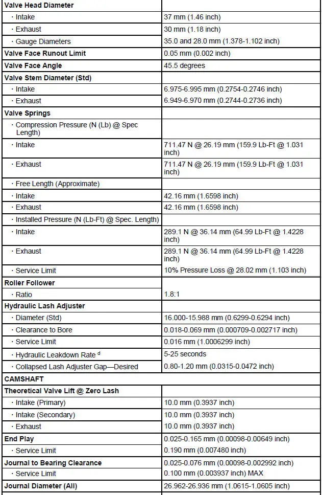
d - Time necessary for plunger to leak down 1.6 mm of travel with 222 N force and leak down fluid in tappet.
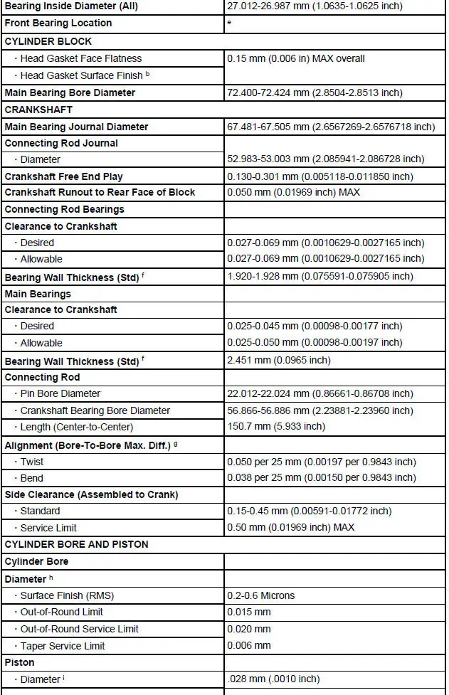
e - Distance front edge of bearing is installed below front face of cylinder block.
f - 0.050 Undersize-add 0.025 to standard thickness.
g - Pin bore and crank bearing bore must be parallel and in same vertical plane within the specified total difference when measured at the ends of a 203 mm bar, 101.5 mm on each side of rod centerline.
h - Cylinder Bore Diameter
Red-90.200-90.213
Blue-90.213-90.226
Yellow-90.226-90.239
i - Measured at 42 mm from piston dome, at 90 degrees to the piston pin.
j - Piston pin outer diameter is larger than piston pin bore, providing a possible interference fit.
k -Specification in 90.200 mm diameter gauge.
l -With installation of a new filter.
Drive Belt Tension
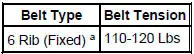
a - "Fixed" refers to systems with manually-adjusted centers which are bolted in place and considered fixed.
Torque Specifications
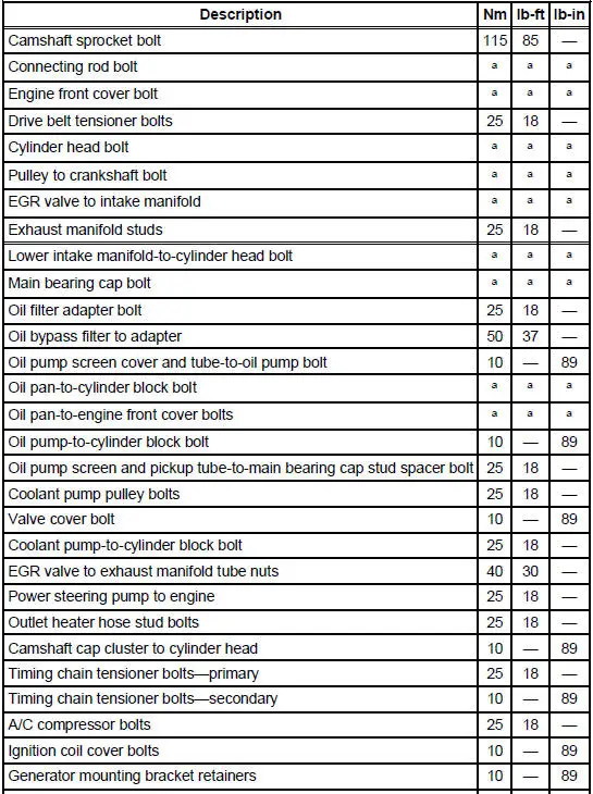
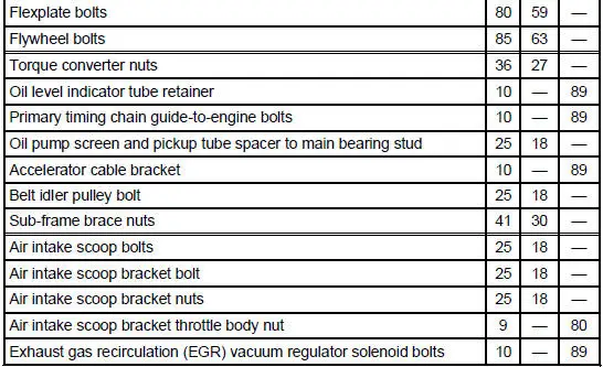
a - Refer to the procedure.
- Engine
- Intake Manifold - Upper
- Intake Manifold - Lower
- Valve Cover RH
- Valve Cover LH
- Engine Front Cover
- Timing Drive Components
- Valve - Springs, Retainer and Valve Stem Seal
- Hydraulic Lash Adjusters
- Roller Followers
- Camshaft
- Exhaust Manifold RH
- Exhaust Manifold LH
- Oil Filter Adapter
- Oil Level Indicator and Tube
- Oil Pan
- Crankshaft Rear Oil Seal
- Engine Mount
- Engine (Removal)
- Engine (Disassembly)
- Cylinder Head
- Piston - Pin Connecting Rod, Floating Pin
- Engine (Assembly)
- Engine (Installation)
 Engine
WARNING: Do not operate the engine with the hood open until the fan
blade has been first
examined for possible cracks and separation.
The 4.6L (4V) (281 CID) is a V-8 engine with the following feat ...
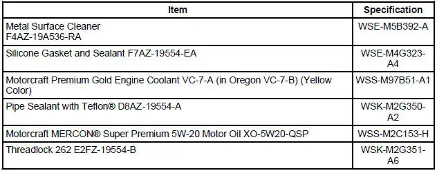
Other materials:
Manual Transmission
The T5OD 5-speed transmission:
fifth speed gear functions as an overdrive gear.
forward gears are synchronized and helical cut.
shift interlock system prevents the engagement of more than one
gear.
Transmission, Manual Five-Speed
T ...
Wipers and Washers (Diagnosis and Testing)
Refer to Wiring Diagrams Cell 59 , Generic Electronic Module for
schematic and connector
information.
Refer to Wiring Diagrams Cell 81 , Interval Wiper/Washer for schematic
and connector information.
Special Tool(s)
Alternator, Regulato ...
Evaporative Emission System Leak Test
Special Tool(s)
Evaporative Emission System
Tester 310-F007
(134-00056) or equivalent
Worldwide Diagnostic System
(WDS)
418-F224,
New Generation STAR (NGS)
Tester
418-F052, or equivalent scan
tool
CAUTION: The evaporat ...
