Ford Mustang (1999-2004) Service Manual: Exhaust System (Description and Operation)
WARNING: The normal operating temperature of the exhaust system is very high. Never attempt to repair any part of the system until it has cooled. Be especially careful when working around the three way catalytic converter. The temperature of the three way catalytic converter rises to a high level after only a few minutes of engine operation.
CAUTION: When repairing exhaust system or removing exhaust components, disconnect all heated oxygen sensors (HO2S) at the wiring connectors to prevent damage to the heated oxygen sensors and wiring harness. For additional information, refer to Section for location of the heated oxygen sensors.
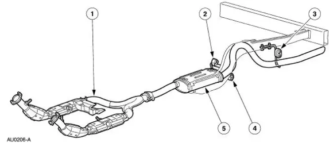
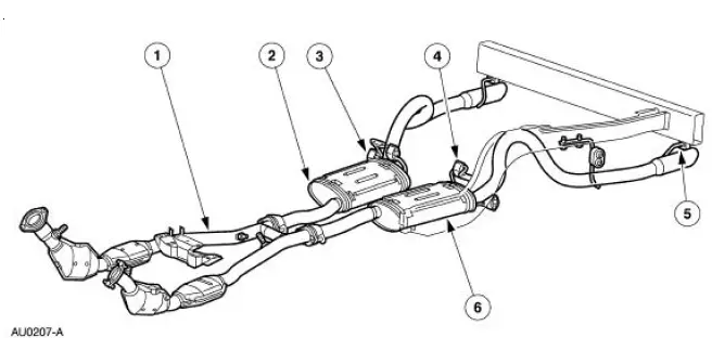
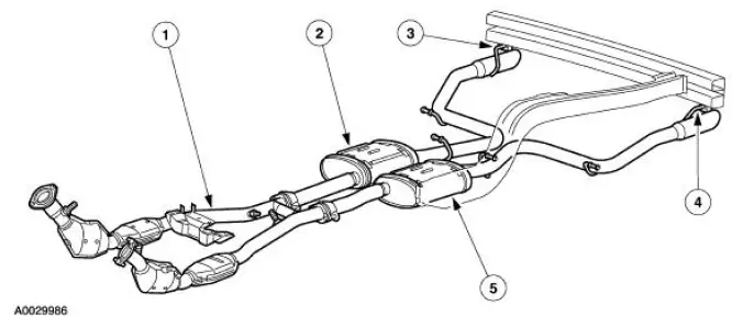
The exhaust system:
- contains dual three-way catalytic converters.
- has a crossover pipe downstream of the three way catalytic converters (4.6L).
- has two upstream heated oxygen sensors mounted before the three-way catalytic converters.
- the production muffler and tailpipe assembly is a one-piece design exhaust system.
Exhaust System - 3.8L
Exhaust System - 4.6L (2V)
Exhaust System - 4.6L (4V)
 Exhaust System
Torque Specifications
...
 Exhaust System (Diagnosis and Testing)
Symptom Chart
Condition
Possible Sources
Action
Noisy or
leaking
exhaust
Broken or loose
clamps, hangers or
isolators.
Punctures in the muffler
( ...
Other materials:
Cleaning the exterior
Wash your vehicle regularly with cool or lukewarm water and a neutral
pH shampoo, such as Motorcraft® Detail Wash.
• Do not use a commercial or high-pressure wand on the surface or
edge of stripes and graphics. This can cause damage to the film and
cause th ...
Selector Lever
Removal
1. Remove the shifter top control panel.
2. Disconnect the electrical connectors.
3. Remove the shifter bezel.
4. Remove the bulb from the bezel.
5. Disconnect the TCS connector.
6. CAUTION: Extra force may be needed to lift up on the handl ...
Pinpoint Test F: LFC 16/DTC B1888 - Passenger Air Bag Circuit Shorted to
Ground
Normal Operation
The restraints control module (RCM) checks for passenger air bag circuit
shorts to ground by
monitoring the voltage of circuits 607 (LB/OG) and 616 (PK/BK) at pins 6 and
7. If the RCM detects a
short to ground on either of these pins, i ...
