Ford Mustang (1999-2004) Service Manual: Sensor - Front
Removal
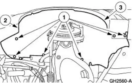
1. Remove the wheel and tire assembly. 2. Remove the inner fender splash shield.
1. Remove the inner fender splash shield push pins.
2. Remove the inner fender splash shield screw.
3. Remove the inner fender splash shield.
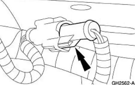
3. Remove the front anti-lock brake sensor electrical connector.
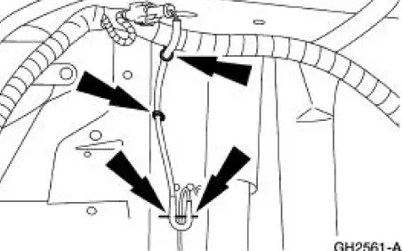
4. Remove the front anti-lock brake sensor harness from the anti-lock brake sensor harness clips.
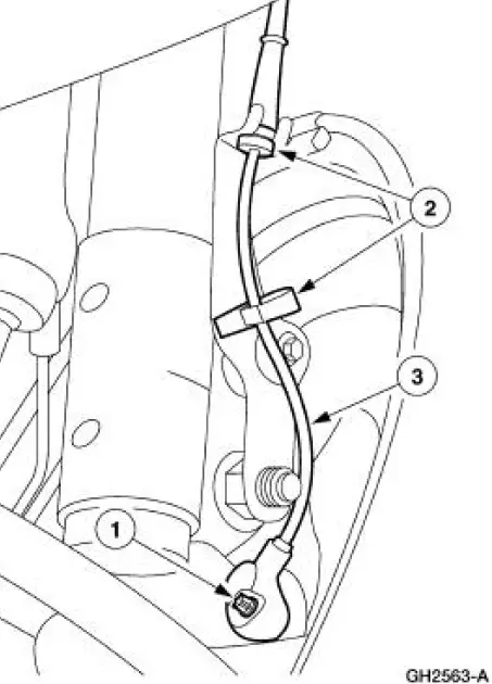
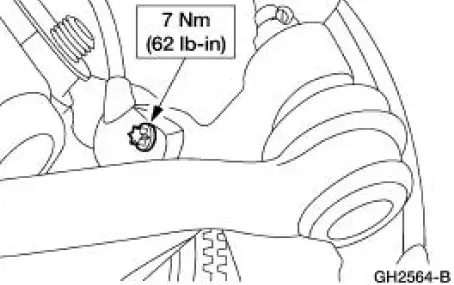
5. Remove the front anti-lock brake sensor.
1. Remove the front anti-lock brake sensor bolt.
2. Remove the anti-lock brake sensor harness from the harness clips.
3. Remove the front anti-lock brake sensor.
Installation
1. To install, reverse the removal procedure.
 Module
Removal
1. Remove the hydraulic control unit (HCU). Refer to Hydraulic Control Unit .
2. Remove the pump motor electrical connector.
3. Remove the anti-lock-brake control module screws.
4. Remove th ...
Other materials:
Pressure Plate Check
1. Check the clutch pressure plate surface for scoring, cracks or
discoloration. Minor scratches or
discoloration should be removed with a fine emery cloth.
2. Measure the flatness of the clutch pressure plate surface with a
straightedge and a feeler
g ...
Installation
1. Position the fuel charging wiring in the vehicle and attach to the rear of
the intake manifold.
2. NOTE: Make sure the locking clips are fully engaged into the bracket.
Reposition the accelerator cable and the speed control cable (if equipped)
and ...
Tracing Powder
Tracing powder is used to check both the uniformity of contact and the
tension of a seal against its
sealing surface. These tests are usually done when a suspected air leak/noise
appears to originate
from the seal area or during the alignment and adjustment ...
