Ford Mustang (1999-2004) Service Manual: Hinge Adjustment
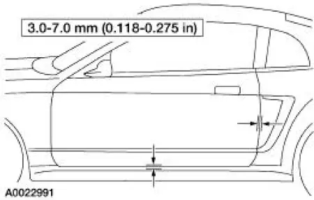
NOTE: The door should be adjusted for even and parallel fit with the body opening and surrounding panels as well as making sure that the anti-chuck pin is not binding on convertible models.
1. Remove the A-pillar lower trim panel.
2. Position the electrical connectors aside.
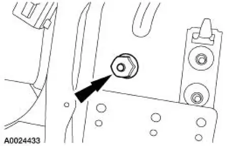
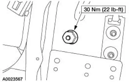
3. Loosen the lower front door hinge-to-body nut enough to permit movement.
4. Remove the fender. For additional information, refer to Section.
5. Mark the position of the upper and lower front door hinges to the body to use as reference points.
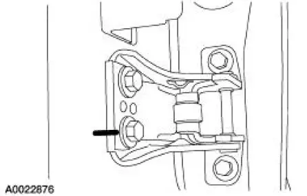
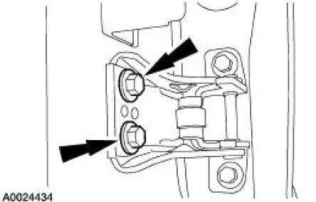
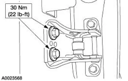
6. Loosen the four upper and lower front door hinge-to-body bolts enough to permit movement.
7. Adjust the front door to specification.
8. NOTE: After adjusting the door hinge, verify that the door can be closed easily and fits tightly.
Tighten the front door hinge to body bolts.
9. Tighten the front door hinge to body nut.
10. Install the electrical connectors.
11. Install the A-pillar lower trim panel.
12. Install the fender. For additional information, refer to Section.
 Body Closures
General Specifications
Torque Specifications
Body Closures
The body closures consist of the following components:
door checks
front door
front door latch strikers
front door hinges ...
 Door Alignment
NOTE: The door should be adjusted for even and parallel fit with the
body opening and surrounding
panels as well as making sure that the anti-chuck pin is not binding on
convertible models.
...
Other materials:
Coupling
Removal and Installation
1. CAUTION: Do not allow the steering column shaft to rotate while
intermediate shaft
is disconnected or damage to the clockspring can result. If there is evidence
that the
steering column shaft has rotated the clockspring must be re ...
Piston - Pin Connecting Rod, Floating Pin
Material
Item
Specification
SAE 5W-20 Premium Synthetic
Blend Engine Oil
XO-5W20-QSP
WSS-M2C153-
H
Disassembly
1. Remove the clips.
2. Remove the piston pin from the piston and connecting rod assembly.
3. Remove the connecting rod ...
Compressor to Condenser Discharge Line - 4.6L
Material
Item
Specification
PAG Refrigerant Compressor
Oil (R-134a Systems)
F7AZ-19589-DA (Motorcraft YN-
12-C)
WSH-M1C231-
B
Removal and Installation
NOTE: Installation of a new suction accumulator is not required when
repairing the ...
