Ford Mustang (1999-2004) Service Manual: Pinpoint Test E: LFC 15/DTC B1916 - Driver Air Bag Circuit Shorted to Battery or Ignition
Normal Operation
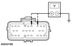
The restraints control module (RCM) checks for driver air bag circuit shorts to battery or ignition by monitoring the voltage of circuit 614 (GY/OG) and 615 (GY/WH) at pins 3 and 4. If the RCM detects a short to battery or ignition on either of these pins, it will store a diagnostic trouble code (DTC) B1916 in memory and flash a lamp fault code (LFC) 15 (or higher priority code if one exists) on the air bag indicator.
Possible Causes
A driver air bag circuit short to battery or ignition can be caused by:
- a short to battery or ignition on circuit 614 (GY/OG).
- a short to battery or ignition on circuit 615 (GY/WH).
- a short to battery or ignition on the clockspring.
- a short to battery or ignition on the driver air bag module.
- an RCM internal concern.
PINPOINT TEST E: LFC 15/DTC B1916 - DRIVER AIR BAG CIRCUIT SHORTED TO BATTERY OR IGNITION
| Test Step | Result / Action to Take |
| E1 CHECK FOR A HARD OR INTERMITTENT DTC | Yes This is a hard fault. The fault condition is still present. This fault cannot be cleared until it is corrected and the DTC is no longer retrieved during the on-demand self test. GO to E2 . No This in an intermittent fault. The fault condition is not present at this time. GO to E5 . |
|
|
| E2 CHECK THE DRIVER AIR BAG MODULE | Yes GO to E3 . No INSTALL a new driver air bag module. GO to E6 . |
| WARNING: If the supplemental restraint system
(SRS) is
being serviced, the system must be deactivated and restraint
system diagnostic tools must be installed. Refer to Air Bag
Supplemental Restraint System (SRS) in this section. The air bag restraint system diagnostic tools must be removed and the air bag modules reconnected when the system is reactivated to avoid non-deployment in a collision, resulting in possible personal injury. NOTE: Diagnostics or repairs are not to be performed on a seat equipped with a seat side air bag with the seat in the vehicle. Prior to attempting to diagnose or repair a seat concern when equipped with a seat side air bag, the seat must be removed from the vehicle and the restraint system diagnostic tools must be installed in the seat side air bag electrical connectors. The restraint system diagnostic tools must be removed prior to operating the vehicle over the road. NOTE: After diagnosing or repairing an SRS, the restraint system diagnostic tools must be removed before operating the vehicle over the road. NOTE: After diagnosing or repairing a seat system, the restraint system diagnostic tools must be removed before operating the vehicle over the road. NOTE: The SRS must be fully operational and free of faults before releasing the vehicle to the customer.
|
|
| E3 CHECK THE DRIVER AIR BAG MODULE CIRCUIT | Yes INSTALL a new RCM. GO to E6 . No GO to E4 . |
|
|
| E4 CHECK THE DRIVER AIR BAG MODULE WIRING AND THE CLOCKSPRING | Yes REPAIR as necessary. GO to E6 . No GO to E6 . |
|
|
| E5 CHECK FOR AN INTERMITTENT FAULT | Yes CHECK for causes of intermittent short to battery or ignition on circuit 614 (GY/OG), circuit 615 (GY/WH), and the clockspring assembly. Attempt to recreate the hard fault by flexing the wire harness and cycling the ignition key frequently. REPAIR any intermittent concerns found. GO to E6 . No GO to E6 . |
|
|
| E6 CHECK FOR ADDITIONAL DTCs | Yes Do not clear any DTCs until all DTCs have been resolved. GO to the Restraints Control Module (RCM) Diagnostic Trouble Code (DTC) Priority Table in this section for pinpoint test direction. No RECONNECT the system. REACTIVATE the system. PROVE OUT the system. REFER to Air Bag Supplemental Restraint System (SRS) in this section. CLEAR all DTCs. |
|
 Pinpoint Test D: LFC 15/DTC B 1887- Driver Air Bag Circuit Shorted to
Ground
Pinpoint Test D: LFC 15/DTC B 1887- Driver Air Bag Circuit Shorted to
Ground
Normal Operation
The restraints control module (RCM) checks for driver air bag circuit
shorts to ground by monitoring the
voltage of circuits 614 (GY/OG) and 615 (GY/WH) at pins 3 and 4. If the RC ...
 Pinpoint Test F: LFC 16/DTC B1888 - Passenger Air Bag Circuit Shorted to
Ground
Pinpoint Test F: LFC 16/DTC B1888 - Passenger Air Bag Circuit Shorted to
Ground
Normal Operation
The restraints control module (RCM) checks for passenger air bag circuit
shorts to ground by
monitoring the voltage of circuits 607 (LB/OG) and 616 (PK/BK) at pins 6 and
7. If t ...
Other materials:
Installation
1. NOTE: Inspect the spring insulators for wear or damage. Install new
spring insulators if
necessary.
Make sure the spring insulators are correctly installed on the springs.
2. Install the springs.
1. Position the springs.
2. Raise the subframe using ...
Transmission (Disassembly)
Special Tool(s)
Bearing Puller
205-D064 (D84L-1123-A) or
Equivalent
Front Hub Tool
204-069 (T81P-1104-C)
Holding Fixture
307-003 (T57L-500-B)
Impact Slide Hammer
100-001 (T50T-100-A)
Puller
...
Link - Stabilizer Bar
Removal
CAUTION: Suspension fasteners are critical parts because they affect
performance of vital
components and systems and their failure can result in major service expense. A
new part with
the same part number must be installed if installation becomes nec ...
