Ford Mustang (1999-2004) Service Manual: Link - Stabilizer Bar
Removal
CAUTION: Suspension fasteners are critical parts because they affect
performance of vital
components and systems and their failure can result in major service expense. A
new part with
the same part number must be installed if installation becomes necessary. If
substitution is
necessary, the part must be of the same finish and property class. Torque values
must be used
as specified during reassembly to make sure of correct retention of these parts.
1. Raise the vehicle on a hoist. For additional information, refer to Section.
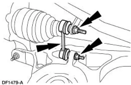
2. NOTE: Spring is removed for clarity.
NOTE: To remove the nuts, first loosen the nut, then use the hex
holding feature to prevent the
stabilizer bar link ball joint from turning while removing the nut.
Remove the nuts and the stabilizer bar links (5C488). Discard the nuts.
Installation
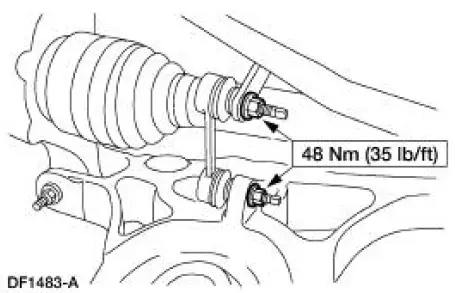
1. NOTE: The nuts on the stabilizer bar links are of a torque prevailing design. New nuts must be used during installation.
NOTE: To install the nuts, first install the nut until snug using the hex holding feature to prevent the stabilizer bar link ball joint from turning. Final tighten the nuts using a socket and a torque wrench.
To install, reverse the removal procedure.
 Stabilizer Bar - Cobra
Removal
CAUTION: Suspension fasteners are critical parts because they affect
performance of vital
components and systems and their failure can result in major service expense. A
new part with
the sa ...
 Wheel Knuckle - Cobra
Special Tool(s)
Front Hub Remover
205-D070 (D93P-1175-B) or
Equivalent
Steering Arm Remover
211-003 (T64P-9171-A)
...
Other materials:
Antenna (Removal and Installation)
Removal
1. Lower the glove compartment by releasing the stops from the
instrument panel.
2. Disconnect the antenna in-line connector
3. Remove the antenna base and cable.
1. Remove the radio antenna base cap.
2. Remove the screws.
3. Re ...
Security Access - Procedure
Special Tool(s)
Worldwide
418-F224,
New Generation STAR (NGS)
Tester
418-F052, or equivalent
diagnostic tool
NOTE: The security access procedure is utilized to obtain passive anti-theft
system (PATS) security
access. PATS security acce ...
Spring Lock Coupling
The spring lock coupling is a refrigerant line coupling held together by a
garter spring inside a circular
cage.
When the coupling is connected together, the flared end of the female
fitting slips behind the
garter spring inside the cage of th ...
