Ford Mustang (1999-2004) Service Manual: Pinpoint Tests
PINPOINT TEST A: NO COMMUNICATION WITH THE INSTRUMENT CLUSTER
| Test Step | Result / Action to Take |
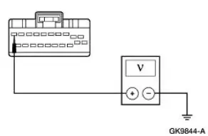
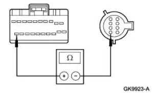
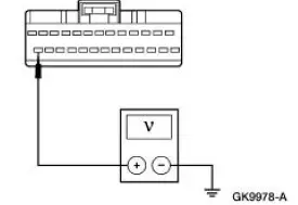
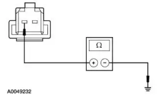
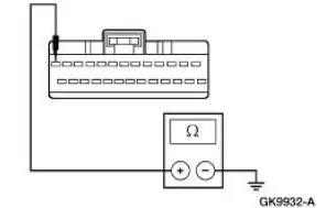
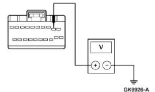
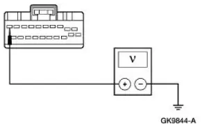
| A1 CHECK THE BATTERY POWER SUPPLY TO THE INSTRUMENT CLUSTER | Yes GO to A2 . No REPAIR the circuit. TEST the system for normal operation. |
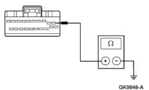
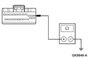
CAUTION: Use the correct probe adapter(s) when
making
measurements. Failure to use the correct probe adapter(s) may
damage the connector.
|
|
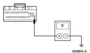
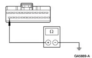
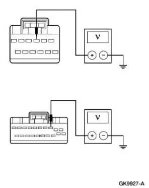
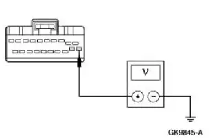
| A2 CHECK THE RUN POWER SUPPLY TO THE INSTRUMENT CLUSTER | Yes GO to A3 . No REPAIR the circuit. TEST the system for normal operation. |
|
|
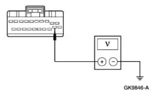
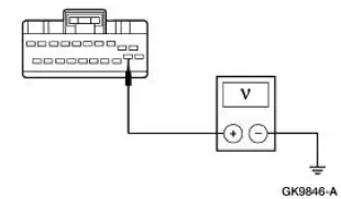
| A3 CHECK THE RUN/START POWER SUPPLY TO THE INSTRUMENT CLUSTER | Yes GO to A4 . No REPAIR the circuit. TEST the system for normal operation. |
|
|
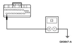
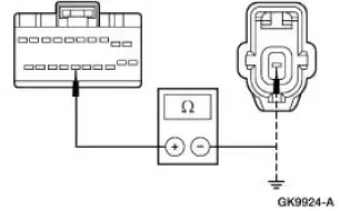
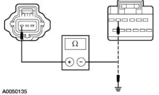
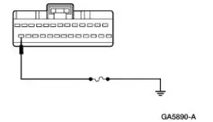
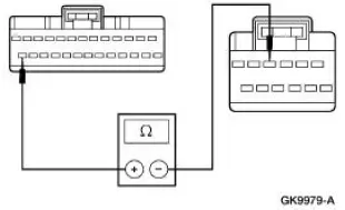
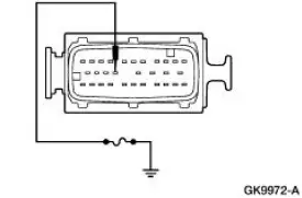
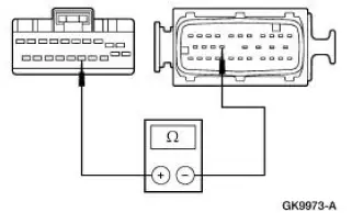
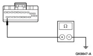
| A4 CHECK GROUND CIRCUIT 397 (BK/WH) FOR AN OPEN | Yes GO to A5 . No REPAIR the circuit. TEST the system for normal operation. |
|
|
| A5 CHECK GROUND CIRCUIT 1205 (BK) FOR OPEN | Yes REFER to Section No REPAIR the circuit. TEST the system for normal operation. |
|
PINPOINT TEST B: INCORRECT FUEL GAUGE INDICATION
| Test Step | Result / Action to Take |
| B1 CARRY OUT THE INSTRUMENT CLUSTER FUEL GAUGE ACTIVE COMMAND | Yes GO to B2 . No GO to B8 . |
CAUTION: Use the correct probe adapter(s) when
making measurements. Failure to use the correct probe
adapter(s) may damage the connector. NOTE: Fuel fills of less
than 9.5 liters (2.5 gallons) require at least 10 minutes to update
the fuel gauge indication.
|
|
| B2 CHECK THE FUEL GAUGE OPERATION | Yes GO to B3 . No GO to B5 . |
|
|
| B3 CHECK THE FUEL TANK | |
|
|
| B4 CHECK THE FUEL PUMP ASSEMBLY | |
|
|
| B5 CHECK CIRCUIT 29 (YE/WH) FOR SHORT TO POWER | Yes REPAIR the circuit. TEST the system for normal operation. No GO to B6 . |
|
|
| B6 CHECK THE FUEL PUMP ASSEMBLY FEED CIRCUIT 29 (YE/WH) | Yes GO to B7 . No REPAIR the circuit. TEST the system for normal operation. |
|
|
| B7 CHECK FUEL PUMP MODULE GROUND CIRCUIT 327 (BK/OG) AND CIRCUIT 397 (BK/WH) | Yes GO to B8 . No REPAIR the circuit(s) in question. TEST the system for normal operation. |
|
|
| B8 CHECK FOR CORRECT INSTRUMENT CLUSTER OPERATION | Yes INSTALL a new instrument cluster. REFER to Instrument Cluster in this section. TEST the system for normal operation. No The system is operating correctly at this time. Concern may have been caused by a loose or corroded connector. CLEAR the DTCs. REPEAT the self-test. |
|
PINPOINT TEST C: INCORRECT OIL PRESSURE GAUGE INDICATION
| Test Step | Result / Action to Take |
| C1 CHECK THE INSTRUMENT CLUSTER OPERATION | Yes GO to C2 . No GO to C3 . |
CAUTION: Use the correct probe adapter(s) when
making measurements. Failure to use the correct probe
adapter(s) may damage the connector.
|
|
| C2 CHECK CIRCUIT 31 (WH/RD) FOR OPEN OR SHORT TO GROUND | Yes INSTALL a new oil pressure switch. TEST the system for normal operation. No REPAIR the circuit. TEST the system for normal operation. |
|
|
| C3 CHECK FOR CORRECT INSTRUMENT CLUSTER OPERATION | Yes INSTALL a new instrument cluster. REFER to Instrument Cluster in this section. TEST the system for normal operation. No The system is operating correctly at this time. Concern may have been caused by a loose or corroded connector. CLEAR the DTCs. REPEAT the self-test. |
|
PINPOINT TEST D: INCORRECT TEMPERATURE GAUGE INDICATION
| Test Step | Result / Action to Take |
| D1 CARRY OUT THE INSTRUMENT CLUSTER ENGINE COOLANT TEMPERATURE GAUGE ACTIVE COMMAND | Yes REFER to the Powertrain Control/Emissions Diagnosis (PC/ED) manual. No GO to D2 . |
|
|
| D2 CHECK FOR CORRECT INSTRUMENT CLUSTER OPERATION | Yes INSTALL a new instrument cluster. REFER to Instrument Cluster in this section. TEST the system for normal operation. No The system is operating correctly at this time. Concern may have been caused by a loose or corroded connector. CLEAR the DTCs. REPEAT the self-test. |
|
PINPOINT TEST E: INCORRECT VOLTAGE GAUGE INDICATION- EXCEPT COBRA
| Test Step | Result / Action to Take |
| E1 CHECK THE INSTRUMENT CLUSTER | Yes GO to E2 . No GO to E4 . |
CAUTION: Use the correct probe adapter(s) when
making measurements. Failure to use the correct probe
adapter(s) may damage the connector.
|
|
| E2 CHECK CHARGING SYSTEM | Yes GO to E3 . No REPAIR the charging system as needed. |
|
|
| E3 CHECK CIRCUIT 904 (LG/RD) FOR OPEN OR SHORT TO GROUND | Yes The system is operating correctly at this time. No REPAIR the circuit. TEST the system for normal operation. |
|
|
| E4 CHECK FOR CORRECT INSTRUMENT CLUSTER OPERATION | Yes INSTALL a new instrument cluster. REFER to Instrument Cluster in this section. TEST the system for normal operation. No The system is operating correctly at this time. Concern may have been caused by a loose or corroded connector. CLEAR the DTCs. REPEAT the self-test. |
|
PINPOINT TEST F: INCORRECT TACHOMETER INDICATION
| Test Step | Result / Action to Take |
| F1 CHECK THE TACHOMETER OPERATION | Yes REFER to the Powertrain Control/Emissions Diagnosis (PC/ED) manual. No GO to F2 . |
|
|
| F2 CHECK FOR CORRECT INSTRUMENT CLUSTER OPERATION | Yes INSTALL a new instrument cluster. REFER to Instrument Cluster in this section. TEST the system for normal operation. No The system is operating correctly at this time. Concern may have been caused by a loose or corroded connector. CLEAR the DTCs. REPEAT the self-test. |
|
PINPOINT TEST G: INCORRECT BOOST GAUGE INDICATION- COBRA ONLY
| Test Step | Result / Action to Take |
| G1 CHECK BOOST GAUGE PRESSURE LINE | Yes CHECK for a plugged manifold fitting. TEST the system for normal operation. No GO to G2 . |
|
|
| G2 CHECK THE BOOST GAUGE | Yes INSTALL a new boost gauge pressure line. TEST the system for normal operation. No INSTALL a new instrument cluster. REFER to Instrument Cluster in this section. TEST the system for normal operation |
|
PINPOINT TEST H: THE LOW FUEL WARNING INDICATOR IS NEVER/ALWAYS ON
| Test Step | Result / Action to Take |
| H1 CARRY OUT THE INSTRUMENT CLUSTER WARNING LAMPS AND CHIME ACTIVE COMMAND USING THE DIAGNOSTIC TOOL | Yes GO to H2 . No GO to H3 . |
|
|
| H2 THE LOW FUEL GAUGE WARNING INDICATOR IS NEVER/ALWAYS ON | Yes GO to H3 . No Go To Pinpoint Test B . |
|
|
| H3 CHECK FOR CORRECT INSTRUMENT CLUSTER OPERATION | Yes INSTALL a new instrument cluster. REFER to Instrument Cluster in this section. TEST the system for normal operation. No The system is operating correctly at this time. Concern may have been caused by a loose or corroded connector. CLEAR the DTCs. REPEAT the self-test. |
|
PINPOINT TEST I: THE SPEEDOMETER IS INOPERATIVE
| Test Step | Result / Action to Take |
| I1 TEST THE INSTRUMENT CLUSTER | Yes REFER to the Powertrain Control/Emissions Diagnosis (PC/ED) manual. No GO to I2 . |
|
|
| I2 CHECK FOR CORRECT INSTRUMENT CLUSTER OPERATION | Yes INSTALL a new instrument cluster. REFER to Instrument Cluster in this section. TEST the system for normal operation. No The system is operating correctly at this time. Concern may have been caused by a loose or corroded connector. CLEAR the DTCs. REPEAT the self-test. |
|
PINPOINT TEST J: THE ODOMETER IS INOPERATIVE
| Test Step | Result / Action to Take |
| J1 CHECK THE ODOMETER DISPLAY | Yes REFER to the Powertrain Control/Emissions Diagnosis (PC/ED) manual. No GO to J2 . |
|
|
| J2 CHECK FOR CORRECT INSTRUMENT CLUSTER OPERATION | Yes INSTALL a new instrument cluster. REFER to Instrument Cluster in this section. TEST the system for normal operation. No The system is operating correctly at this time. Concern may have been caused by a loose or corroded connector. CLEAR the DTCs. REPEAT the self-test. |
|
PINPOINT TEST K: THE SAFETY BELT INDICATOR IS INOPERATIVE (CHIME IS OPERATIVE)/DOES NOT OPERATE CORRECTLY
| Test Step | Result / Action to Take |
| K1 CHECK IF THE GEM IS RECEIVING THE CORRECT IGNITION SWITCH STATUS | Yes GO to K2 . No REFER to Section |
CAUTION: Use the correct probe adapter(s) when making measurements. Failure to use the correct probe adapter(s) may damage the connector.
|
|
| K2 CHECK IF THE GEM IS RECEIVING THE CORRECT SAFETY BELT SWITCH STATUS | Yes GO to K3 . No REFER to Section |
|
|
| K3 CHECK THE GEM FOR INTERNAL OPEN OR SHORT | Yes GO to K10 . No GO to K4 . |
|
|
| K4 DETERMINE IF SAFETY BELT INDICATOR CIRCUIT IS SHORTED TO GROUND | Yes GO to K5 . No GO to K7 . |
|
|
| K5 CHECK IF THE GEM IS INTERNALLY GROUNDED | Yes GO to K6 . No GO to K10 . |
|
|
| K6 CHECK CIRCUIT 450 (DG/LG) FOR A SHORT TO GROUND | Yes GO to K11 . No REPAIR the circuit. TEST the system for normal operation. |
|
|
| K7 CHECK CIRCUIT 450 (DG/LG) FOR A SHORT TO BATTERY | Yes REPAIR the circuit. TEST the system for normal operation. No GO to K8 . |
|
|
| K8 CHECK THE GEM MODULE FOR AN INTERNAL OPEN | Yes GO to K10 . No GO to K9 . |
|
|
| K9 CHECK CIRCUIT 450 (DG/LG) FOR AN OPEN | Yes GO to K11 . No REPAIR the circuit. TEST the system for normal operation. |
|
|
| K10 CHECK FOR CORRECT GEM OPERATION | Yes INSTALL a new GEM. REFER to Section. TEST the system for normal operation. No The system is operating correctly at this time. Concern may have been caused by a loose or corroded connector. CLEAR the DTCs. REPEAT the selftest. |
|
|
| K11 CHECK FOR CORRECT INSTRUMENT CLUSTER OPERATION | Yes INSTALL a new instrument cluster. REFER to Instrument Cluster in this section. TEST the system for normal operation. No The system is operating correctly at this time. Concern may have been caused by a loose or corroded connector. CLEAR the DTCs. REPEAT the selftest. |
|
PINPOINT TEST L: INACCURATE SPEEDOMETER READING
| Test Step | Result / Action to Take |
| L1 CHECK SPEEDOMETER OPERATION | Yes REFER to the Powertrain Control/Emissions Diagnosis (PC/ED) manual. No GO to L2 . |
|
|
| L2 CHECK FOR CORRECT INSTRUMENT CLUSTER OPERATION | Yes INSTALL a new instrument cluster. REFER to Instrument Cluster in this section. TEST the system for normal operation. No The system is operating correctly at this time. Concern may have been caused by a loose or corroded connector. CLEAR the DTCs. REPEAT the self-test. |
|
PINPOINT TEST M: THE O/D OFF INDICATOR IS NEVER ON
| Test Step | Result / Action to Take |
| M1 CHECK THE O/D OFF INDICATOR OPERATION | Yes GO to M2 . No GO to M3 . |
|
|
| M2 CHECK THE INSTRUMENT CLUSTER | Yes REFER to the Powertrain Control/Emissions Diagnosis (PC/ED) manual. No GO to M4 . |
|
|
| M3 CHECK THE INSTRUMENT CLUSTER OPERATION | Yes REFER to the Powertrain Control/Emissions Diagnosis (PC/ED) manual. No GO to M4 . |
|
|
| M4 CHECK FOR CORRECT INSTRUMENT CLUSTER OPERATION | Yes INSTALL a new instrument cluster. REFER to Instrument Cluster in this section. TEST the system for normal operation. No The system is operating correctly at this time. Concern may have been caused by a loose or corroded connector. CLEAR the DTCs. REPEAT the self-test. |
|
PINPOINT TEST N: THE CHECK FUEL CAP INDICATOR IS NEVER ON
| Test Step | Result / Action to Take |
| N1 RETREIVE AND RECORD DTCS FROM CONTINUOUS AND ON-DEMAND SELF-TESTS- PCM | Yes If PCM DTC P0457, REFER to the Powertrain Control/Emissions Diagnosis (PC/ED) manual. No GO to N2 . |
NOTE: Once the check fuel cap indicator does turn on, it does not turn off unless the fuel cap has been correctly secured and the vehicle has been driven for several minutes.
|
|
| N2 CARRY OUT THE INSTRUMENT CLUSTER INDICATOR LAMP CONTROL III ACTIVE COMMAND USING THE DIAGNOSTIC TOOL | Yes REFER to the Powertrain Control/Emissions Diagnosis (PC/ED) manual. No GO to N3 . |
|
|
| N3 CHECK FOR CORRECT INSTRUMENT CLUSTER OPERATION | Yes INSTALL a new instrument cluster. REFER to Instrument Cluster in this section. TEST the system for normal operation. No The system is operating correctly at this time. Concern may have been caused by a loose or corroded connector. CLEAR the DTCs. REPEAT the self-test. |
|
PINPOINT TEST O: THE BRAKE WARNING INDICATOR IS NEVER/ALWAYS ON
| Test Step | Result / Action to Take |
| O1 CHECK IF THE GEM IS RECEIVING THE CORRECT IGNITION SWITCH STATUS | Yes GO to O2 . No REFER to Section |
CAUTION: Use the correct probe adapter(s) when making measurements. Failure to use the correct probe adapter(s) may damage the connector.
|
|
| O2 DETERMINE IF GEM IS RECEIVING THE CORRECT PARKING BRAKE INPUT | Yes GO to O3 . No GO to O5 . |
|
|
| O3 DETERMINE IF BRAKE WARNING INDICATOR CIRCUIT IS OPEN OR GROUNDED | Yes GO to O4 . No GO to O11 |
|
|
| O4 DETERMINE IF GEM IS SENDING THE CORRECT OUTPUT SIGNAL | Yes GO to O14 . No GO to O9 . |
|
|
| O5 CHECK CIRCUIT BETWEEN THE PARKING BRAKE SWITCH AND THE GEM FOR A SHORT TO GROUND | Yes GO to O8 . No GO to O6 |
|
|
| O6 CHECK CIRCUIT 128 (VT/YE) AND CIRCUIT 22 (LB/BK) FOR AN OPEN | Yes GO to O7 . No REPAIR the circuit. TEST the system for normal operation. |
|
|
| O7 CHECK CIRCUIT 1205 (BK) FOR OPEN | Yes INSTALL a new parking brake switch. TEST the system for normal operation. No REPAIR the circuit. TEST the system for normal operation. |
|
|
| O8 CHECK CIRCUIT 128 (VT/YE) FOR A SHORT TO GROUND | Yes REPAIR or INSTALL a new parking brake switch as needed. TEST the system for normal operation. No REPAIR the circuit. TEST the system for normal operation. |
|
|
| O9 CHECK CIRCUIT 128 (VT/YE) FOR SHORT TO BATTERY | Yes REPAIR the circuit. TEST the system for normal operation. No GO to O10 . |
|
|
| O10 CHECK CIRCUIT 128 (VT/YE) FOR AN OPEN | Yes GO to O15 . No REPAIR the circuit. TEST the system for normal operation. |
|
|
| O11 CHECK THE BRAKE FLUID LEVEL SWITCH FOR AN INTERNAL GROUND | Yes GO to O12 . No INSTALL a new brake fluid level switch. TEST the system for normal operation. |
|
|
| O12 DETERMINE IF THE GEM IS INTERNALLY GROUNDED | Yes GO to O13 . No GO to O14 . |
|
|
| O13 CHECK CIRCUIT 128 (VT/YE) FOR SHORT TO GROUND BETWEEN GEM AND INSTRUMENT CLUSTER | Yes GO to O15 . No REPAIR the circuit. TEST the system for normal operation. |
|
|
| O14 CHECK FOR CORRECT GEM OPERATION | Yes INSTALL a new GEM. REFER to Section. TEST the system for normal operation. No The system is operating correctly at this time. Concern may have been caused by a loose or corroded connector. CLEAR the DTCs. REPEAT the self-test. |
|
|
| O15 CHECK FOR CORRECT INSTRUMENT CLUSTER OPERATION | Yes INSTALL a new instrument cluster. REFER to Instrument Cluster in this section. TEST the system for normal operation. No The system is operating correctly at this time. Concern may have been caused by a loose or corroded connector. CLEAR the DTCs. REPEAT the self-test. |
|
PINPOINT TEST P: THE CHARGING SYSTEM WARNING INDICATOR IS NEVER/ALWAYS ON
| Test Step | Result / Action to Take |
| P1 CHECK THE CHARGING SYSTEM | Yes GO to P2 . No REFER to Section |
CAUTION: Use the correct probe adapter(s) when making measurements. Failure to use the correct probe adapter(s) may damage the connector.
|
|
| P2 CHECK CHARGING SYSTEM WARNING INDICATOR WITH ENGINE OFF | Yes GO to P5 . No GO to P3 . |
|
|
| P3 CHECK THE INSTRUMENT CLUSTER INPUT | Yes INSTALL a new generator. REFER to Section. TEST the system for normal operation. No GO to P4 . |
|
|
| P4 CHECK CIRCUIT 904 (LG/RD) FOR OPEN | Yes GO to P7 . No REPAIR the circuit. TEST the system for normal operation. |
|
|
| P5 CHECK THE GENERATOR | Yes GO to P6 . No INSTALL a new generator. REFER to Section. TEST the system for normal operation. |
|
|
| P6 CHECK CIRCUIT 904 (LG/RD) FOR SHORT TO GROUND | Yes GO to P7 . No REPAIR the circuit. TEST the system for normal operation. |
|
|
| P7 CHECK FOR CORRECT INSTRUMENT CLUSTER OPERATION | Yes INSTALL a new instrument cluster. REFER to Instrument Cluster in this section. TEST the system for normal operation. No The system is operating correctly at this time. Concern may have been caused by a loose or corroded connector. CLEAR the DTCs. REPEAT the self-test. |
|
PINPOINT TEST Q: THE HIGH BEAM INDICATOR IS NEVER/ALWAYS ON
| Test Step | Result / Action to Take |
| Q1 CHECK THE HIGH BEAM LAMP OPERATION | Yes GO to Q2 . No REFER to Section |
CAUTION: Use the correct probe adapter(s) when making measurements. Failure to use the correct probe adapter(s) may damage the connector.
|
|
| Q2 CHECK CIRCUIT 932 (GY/WH) AND CIRCUIT 12 (LG/BK) FOR AN OPEN | Yes GO to Q3 . No REPAIR the circuit. TEST the system for normal operation. |
|
|
| Q3 CHECK FOR CORRECT INSTRUMENT CLUSTER OPERATION | Yes INSTALL a new instrument cluster. REFER to Instrument Cluster in this section. TEST the system for normal operation. No The system is operating correctly at this time. Concern may have been caused by a loose or corroded connector. CLEAR the DTCs. REPEAT the selftest. |
|
PINPOINT TEST R: THE ABS WARNING INDICATOR IS NEVER ON
| Test Step | Result / Action to Take |
| R1 CHECK THE ABS WARNING INDICATOR OPERATION | Yes The system is operating normally at this time. No If the indicator is inoperative, GO to R2 . If the indicator is always on, REFER to Section |
CAUTION: Use the correct probe adapter(s) when making measurements. Failure to use the correct probe adapter(s) may damage the connector.
|
|
| R2 CHECK THE INSTRUMENT CLUSTER INPUT | Yes REFER to Section No GO to R3 . |
|
|
| R3 CHECK CIRCUIT 603 (DG) FOR AN OPEN | Yes GO to R4 . No REPAIR the circuit. TEST the system for normal operation. |
|
|
| R4 CHECK FOR CORRECT INSTRUMENT CLUSTER OPERATION | Yes INSTALL a new instrument cluster. REFER to Instrument Cluster in this section. TEST the system for normal operation. No The system is operating correctly at this time. Concern may have been caused by a loose or corroded connector. CLEAR the DTCs. REPEAT the self-test. |
|
PINPOINT TEST S: THE SERVICE ENGINE SOON INDICATOR IS NEVER/ALWAYS ON
| Test Step | Result / Action to Take |
| S1 CARRY OUT THE INSTRUMENT CLUSTER SERVICE ENGINE SOON INDICATOR ACTIVE COMMAND | Yes REFER to the Powertrain Control/Emissions Diagnosis (PC/ED) manual. No GO to S2 . |
|
|
| S2 CHECK FOR CORRECT INSTRUMENT CLUSTER OPERATION | Yes INSTALL a new instrument cluster. REFER to Instrument Cluster in this section. TEST the system for normal operation. No The system is operating correctly at this time. Concern may have been caused by a loose or corroded connector. CLEAR the DTCs. REPEAT the self-test. |
|
PINPOINT TEST T: THE TURN/HAZARD INDICATOR IS NEVER/ALWAYS ON
| Test Step | Result / Action to Take |
| T1 CHECK THE TURN SIGNAL AND HAZARD LAMPS OPERATION | Yes GO to T2 . No REFER to Section |
CAUTION: Use the correct probe adapter(s) when making measurements. Failure to use the correct probe adapter(s) may damage the connector.
|
|
| T2 CHECK THE CIRCUIT IN QUESTION - CIRCUIT 2 (WH/LB) (RH) OR CIRCUIT 3 (LG/WH) (LH) | Yes GO to T3 . No REPAIR the circuit (s) in question. TEST the system for normal operation. |
|
|
| T3 CHECK FOR CORRECT INSTRUMENT CLUSTER OPERATION | Yes INSTALL a new instrument cluster. REFER to Instrument Cluster in this section. TEST the system for normal operation. No The system is operating correctly at this time. Concern may have been caused by a loose or corroded connector. CLEAR the DTCs. REPEAT the self-test. |
|
PINPOINT TEST U: THE TRACTION CONTROL INDICATOR IS NEVER/ALWAYS ON
| Test Step | Result / Action to Take |
| U1 DETERMINE IF THE TRACTION CONTROL INDICATOR IS ALWAYS ON | Yes REFER to Section. No GO to U2 . |
|
|
| U2 DETERMINE IF INSTRUMENT CLUSTER IS AT FAULT | Yes REFER to Section. No GO to U3 . |
|
|
| U3 CHECK FOR CORRECT INSTRUMENT CLUSTER OPERATION | Yes INSTALL a new instrument cluster. REFER to Instrument Cluster in this section. TEST the system for normal operation. No The system is operating correctly at this time. Concern may have been caused by a loose or corroded connector. CLEAR the DTCs. REPEAT the self-test. |
|
PINPOINT TEST V: THE INSTRUMENT CLUSTER IS INOPERATIVE
| Test Step | Result / Action to Take |
| V1 CHECK THE BATTERY POWER SUPPLY TO THE INSTRUMENT CLUSTER | Yes GO to V2 . No REPAIR the circuit. TEST the system for normal operation. |
CAUTION: Use the correct probe adapter(s) when making measurements. Failure to use the correct probe adapter(s) may damage the connector.
|
|
| V2 CHECK THE RUN POWER SUPPLY TO THE INSTRUMENT CLUSTER | Yes GO to V3 . No REPAIR the circuit. TEST the system for normal operation. |
|
|
| V3 CHECK RUN/START POWER SUPPLY TO THE INSTRUMENT CLUSTER | Yes GO to V4 . No REPAIR the circuit. TEST the system for normal operation. |
|
|
| V4 CHECK GROUND CIRCUIT 397 (BK/WH) FOR AN OPEN | Yes GO to V5 . No REPAIR the circuit. TEST the system for normal operation. |
|
|
| V5 CHECK GROUND CIRCUIT 1205 (BK) FOR OPEN | Yes GO to V6 . No REPAIR the circuit. TEST the system for normal operation. |
|
|
| V6 CHECK FOR CORRECT INSTRUMENT CLUSTER OPERATION | Yes INSTALL a new instrument cluster. REFER to Instrument Cluster in this section. TEST the system for normal operation. No The system is operating correctly at this time. Concern may have been caused by a loose or corroded connector. CLEAR the DTCs. REPEAT the selftest. |
|
PINPOINT TEST W: NO COMMUNICATION WITH THE GENERIC ELECTRONIC MODULE (GEM)
| Test Step | Result / Action to Take |
| CAUTION: Use the correct probe adapter(s) when making measurements. Failure to use the correct probe adapter(s) may damage the connector. | |
| W1 CHECK THE GENERIC ELECTRONIC MODULE (GEM) POWER SUPPLY | Yes GO to W2 . No REPAIR the circuit(s) in question. TEST the system for normal operation. |
|
|
| W2 CHECK THE GEM GROUND CIRCUIT 397 (BK/WH) FOR OPEN | Yes GO to W3 . No REPAIR the circuit(s) in question. TEST the system for normal operation. |
|
|
| W3 CHECK CIRCUIT 397 (BK/WH) FOR SHORT TO POWER | Yes REPAIR the circuit. TEST the system for normal operation. No REFER to Section. |
|
|
 Instrument Cluster Self-Diagnostic Mode
To enter the instrument cluster self-diagnostic mode, press and hold the
instrument cluster
SELECT/RESET button, turn the ignition switch to the RUN position, and then
continue pressing the
SELE ...

Other materials:
Disassembly
1. Inspect the clutch cylinder thrust surfaces, piston bore and clutch plate
serrations for scores or
burrs. Minor scores or burrs may be removed with a crocus cloth. Install a new
clutch cylinder if
badly scored or damaged.
2. Check fluid passage in the cl ...
Analysis of Vibration
WARNING: A vehicle equipped with a Traction-Lok differential will
always have both
wheels driving. If only one wheel is raised off the floor and the rear axle is
driven by the engine,
the wheel on the floor could drive the vehicle off the stand or jack. Be s ...
Removal
WARNING: Always wear safety glasses when repairing an air bag
supplemental restraint
system (SRS) vehicle and when handling an air bag module. This will
reduce the risk of injury
in the event of an accidental deployment.
WARNING: Carry a live air ...
