Ford Mustang (1999-2004) Service Manual: Control Valve
Removal
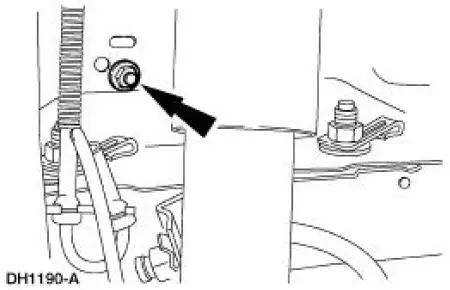
1. Disconnect the brake tubes.
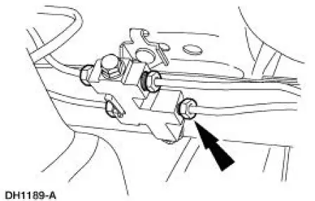
2. Remove the brake fluid control valve bracket nut.
Installation
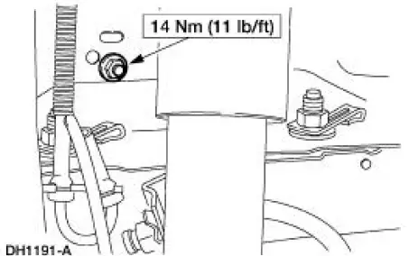
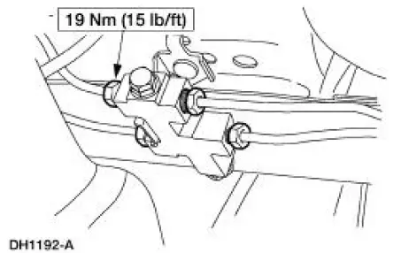
1. To install, reverse the removal procedure.
 Reservoir
Removal
WARNING: Brake fluid contains polyglycol ethers and polyglycols.
Avoid contact with
eyes. Wash hands thoroughly after handling. If brake fluid contacts eyes,
flush eyes with
running wat ...
 Power Brake Actuation
Torque Specifications
...
Other materials:
Heated seats
WARNING: Persons who are unable to feel pain to the skin
because of advanced age, chronic illness, diabetes, spinal cord
injury, medication, alcohol use, exhaustion, or other physical conditions,
must exercise care when using the seat heater. The seat heater m ...
Engine (Disassembly)
Special Tool(s)
Service Set, Camshaft
303-017 (T65L-6250-A)
Remover, Crankshaft Vibration
Damper
303-009 (T58P-6316-D)
Lifting Bracket Set, Engine
303-D095 (D94L-6001-A) or
equivalent
Remover, Power Stee ...
Installation
1. Overlay the new rear window glass assembly over the old rear
window glass assembly and
transpose the markings with a grease pencil.
2. Center the V-notch on the new rear window glass assembly to the
center mark on the top of the
number four bow ...
