Ford Mustang (1999-2004) Service Manual: Instrument Cluster (Diagnosis and Testing)
Refer to Wiring Diagrams Cell 60 , Instrument Cluster for schematic and connector information.
Special Tool(s)
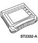 |
Worldwide Diagnostic System (WDS) 418-F224, New Generation STAR (NGS) Tester 418-F052, or equivalent diagnostic tool |
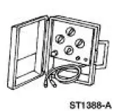 |
Instrument Gauge System Tester 014-R1063 or equivalent |
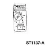 |
73III Automotive Meter 105-R0057 or equivalent |
- Principles of Operation
- Instrument Cluster Replacement
- Inspection and Verification
- Instrument Cluster Self-Diagnostic Mode
- Pinpoint Tests
 Instrument Cluster (Description and Operation)
The instrument cluster (10849) consists of the following components:
Instrument Cluster-Base 3.8L Engine
Instrument Cluster-Base 4.6L Engine
Instrument Cluster-Cobra
...
 Principles of Operation
NOTE: A new instrument cluster must be reconfigured. Refer to
Section.
The instrument cluster is a hybrid electronic cluster (HEC). The
instrument cluster uses both hardwired
and the standard co ...
Other materials:
Reversing Lamps
Refer to Wiring Diagrams Cell 93 , Backup Lamps for schematic and
connector information.
Special Tool(s)
73III Automotive Meter or
equivalent
105-R0057
Inspection and Verification
1. Verify the customer concern by operating the reversing l ...
Exhaust Manifold RH
Special Tool(s)
Lifting Bracket, Engine
303-D088 (D93P-6001-A2)
Support Bar, Engine
303-290-A
Removal and Installation
1. Install the special tool.
2. Install the special tools.
3. Raise and support the vehicle. For additional ...
Roadside assistance
Vehicles Sold in the U.S.: Getting Roadside Assistance
To fully assist you should you have a vehicle concern, Ford Motor
Company offers a complimentary roadside assistance program.
This program is separate from the New Vehicle Limited Warranty.
The service i ...
