Ford Mustang (1999-2004) Service Manual: Pinpoint Tests
CAUTION: Before removing and installing the generic electronic module (GEM) or its connectors, disconnect the battery. Failure to follow this caution will result in the GEM storing many erroneous DTCs, and it may exhibit erratic operation after installation.
CAUTION: Be careful when probing the central junction box (CJB), or any connectors.
Damage will result to the connector receptacle if the probe or terminal used is too large.
CAUTION: Electronic modules are sensitive to static discharges. If exposed to these charges, damage may result.
NOTE: If continuous DTCs are recorded and the symptom is not present when carrying out the pinpoint tests, an intermittent concern may be the cause. Always check for loose connections and corroded terminals.
Complete the entire pinpoint test related to the symptom before installing a new GEM.
PINPOINT TEST A: NO COMMUNICATION WITH THE GENERIC ELECTRONIC MODULE (GEM)
| Test Step | Result / Action to Take |
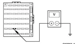
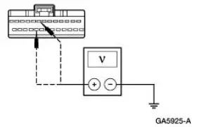
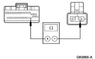
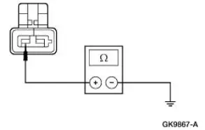
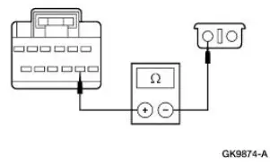
| A1 CHECK THE GENERIC ELECTRONIC MODULE (GEM) POWER SUPPLY | Yes GO to A2 . No REPAIR the circuit(s) in question. TEST the system for normal operation. |
|
|
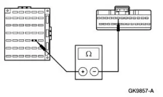
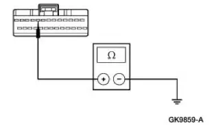
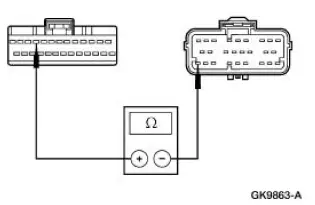
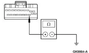
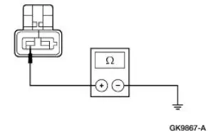
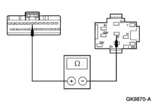
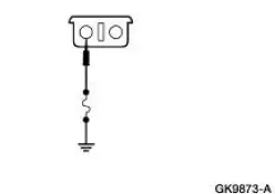
| A2 CHECK THE GEM GROUND CIRCUIT 397 (BK/WH) FOR OPEN | Yes GO to A3 . No REPAIR the circuit(s) in question. TEST the system for normal operation. |
|
|
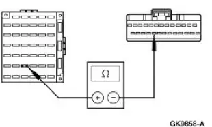
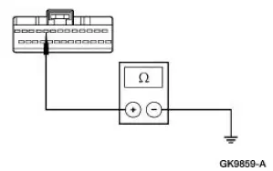
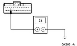
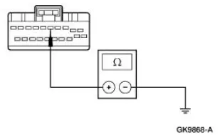
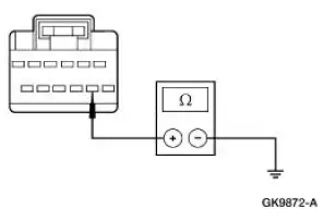
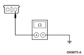
| A3 CHECK CIRCUIT 397 (BK/WH) FOR SHORT TO POWER | Yes REPAIR the circuit. TEST the system for normal operation. No REFER to Section |
|
PINPOINT TEST B: THE KEY-IN-IGNITION CHIME DOES NOT OPERATE CORRECTLY
| Test Step | Result / Action to Take |
| B1 CHECK IGNITION STATES | Yes GO to B2 . No GO to B4 . |
|
|
| B2 CHECK GEM INTERNAL TONE OPERATION | Yes GO to B3 . No GO to B11 . |
|
|
| B3 CHECK GEM INPUT FROM DOOR AJAR CIRCUIT | Yes GO to B11 . No Go To Pinpoint Test D . |
|
|
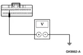
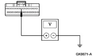
| B4 CHECK GEM INPUT VOLTAGE FROM IGNITION SWITCH AT CJB FUSE 28 (15A) | Yes GO to B5 . No REPAIR the CJB. REPEAT the self-test. CLEAR the DTCs. |
|
|
| B5 CHECK GEM INPUT VOLTAGE FROM IGNITION SWITCH AT CJB FUSE 32 (15A) | Yes GO to B6 . No REPAIR the CJB. REPEAT the self-test. CLEAR the DTCs. |
|
|
| B6 CHECK GEM VOLTAGE INPUT CIRCUITS FOR OPEN - IGNITION SWITCH CIRCUIT 911 (WH/LG) | Yes GO to B7 . No REPAIR the circuit. REPEAT the self-test. CLEAR the DTCs. |
|
|
| B7 CHECK GEM VOLTAGE INPUT CIRCUITS FOR OPEN - IGNITION SWITCH CIRCUIT 1002 (BK/PK) | Yes GO to B8 . No REPAIR the circuit. REPEAT the self-test. CLEAR the DTCs. |
|
|
| B8 CHECK GEM INPUT CIRCUIT FOR OPEN - KEY-INIGNITION SWITCH CIRCUIT 158 (BK/PK) | Yes GO to B9 . No REPAIR circuit 158 (BK/PK) and key-inignition switch for failure. REFER to Switch-Key- In-Ignition Warning . REPEAT the self-test. CLEAR the DTCs. |
|
|
| B9 CHECK GEM VOLTAGE INPUT CIRCUITS FOR SHORT TO POWER - IGNITION SWITCH CIRCUITS 911 (WH/LG), AND 1002 (BK/PK) | Yes REPAIR the circuit in question. REPEAT the self-test. CLEAR the DTCs. No GO to B10 . |
|
|
| B10 CHECK GEM INPUT CIRCUIT FOR SHORT TO GROUND -- KEY-IN-IGNITION SWITCH CIRCUIT 158 (BK/PK) | Yes GO to B11 . No REPAIR the circuit. REPEAT the self-test. CLEAR the DTCs. |
|
|
| B11 CHECK FOR CORRECT MODULE OPERATION | Yes INSTALL a new GEM. REFER to Section. CLEAR the DTCs. REPEAT the GEM selftest. No The system is operating correctly at this time. Concern may have been caused by a loose or corroded connector. CLEAR the DTCs. REPEAT the self-test. |
|
PINPOINT TEST C: A CHIME DOES NOT OPERATE CORRECTLY- AIR BAG
| Test Step | Result / Action to Take |
| C1 CHECK CONTINUOUS DTCS AND RESTRAINT CONTROL MODULE (RCM) | Yes REFER to Section. No GO to C2 . |
|
|
| C2 CHECK IGNITION STATES | Yes GO to C3 . No Go To Pinpoint Test B . |
|
|
| C3 CHECK GEM INTERNAL TONE OPERATION | Yes GO to C4 . No GO to C8 . |
|
|
| C4 CHECK GEM INPUT FROM RCM - AIR BAG WARNING CHIME | Yes GO to C5 . No GO to C6 . |
|
|
| C5 CHECK CIRCUIT 1083 (LB/BK) FOR SHORT TO GROUND | Yes GO to C8 . No REPAIR the circuit. REPEAT the self-test. CLEAR the DTCs. |
|
|
| C6 CHECK CIRCUIT 1083 (LB/BK) FOR SHORT TO POWER | Yes REPAIR the circuit. REPEAT the self-test. CLEAR the DTCs. No GO to C7 . |
|
|
| C7 CHECK CIRCUIT 1083 (LB/BK) FOR OPEN | Yes GO to C8 . No REPAIR the circuit. REPEAT the self-test. CLEAR the DTCs. |
|
|
| C8 CHECK FOR CORRECT MODULE OPERATION | Yes INSTALL a new GEM. REFER to Section 419-10 . CLEAR the DTCs. REPEAT the GEM self-test. No The system is operating correctly at this time. Concern may have been caused by a loose or corroded connector. CLEAR the DTCs. REPEAT the selftest. |
|
PINPOINT TEST D: THE DOOR AJAR CHIME DOES NOT OPERATE CORRECTLY
| Test Step | Result / Action to Take |
| D1 CHECK IGNITION STATES | Yes GO to D2 . No GO to Pinpoint Test B . |
|
|
| D2 CHECK GEM INTERNAL TONE OPERATION | Yes GO to D3 . No GO to D17 . |
|
|
| D3 CHECK GEM INPUT - DRIVER DOOR AJAR CIRCUIT | Yes GO to D4 . No GO to D5 . |
|
|
| D4 CHECK GEM INPUT - PASSENGER DOOR AJAR CIRCUIT | Yes GO to D17 . No GO to D11 |
|
|
| D5 CHECK CIRCUIT 765 (YE/BK) AND DRIVER DOOR AJAR SWITCH FOR OPEN OR SHORT TO GROUND | Yes GO to D6 . No GO to D8 . |
|
|
| D6 ISOLATE SHORT TO GROUND ON CIRCUIT 765 (YE/BK) | Yes INSTALL a new driver door ajar switch. REFER to Section. REPEAT the self-test. CLEAR the DTCs. No GO to D7 . |
|
|
| D7 CHECK CIRCUIT 765 (YE/BK) FOR SHORT TO GROUND BETWEEN GEM AND DRIVER DOOR AJAR SWITCH | Yes GO to D17 . No REPAIR the circuit. REPEAT the self-test. CLEAR the DTCs. |
|
|
| D8 CHECK CIRCUIT 765 (YE/BK) FOR OPEN | Yes GO to D10 . No GO to D9 . |
|
|
| D9 CHECK CIRCUIT 765 (YE/BK) FOR OPEN BETWEEN GEM AND DRIVER DOOR AJAR SWITCH | Yes GO to D17 . No REPAIR the circuit. REPEAT the self-test. CLEAR the DTCs. |
|
|
| D10 CHECK CIRCUIT 1205 (BK) FOR OPEN BETWEEN DRIVER DOOR AJAR SWITCH AND GROUND | Yes INSTALL a new driver door ajar switch. REFER to Section. REPEAT the self-test. CLEAR the DTCs. No REPAIR the circuit. REPEAT the self-test. CLEAR the DTCs. |
|
|
| D11 ISOLATE OPEN OR SHORT TO GROUND ON CIRCUIT 761 (GN/RD) | Yes GO to D12 . No GO to D14 . |
|
|
| D12 ISOLATE SHORT TO GROUND ON CIRCUIT 761 (GN/RD) | Yes INSTALL a new passenger door ajar switch. REFER to Section. REPEAT the self-test. CLEAR the DTCs. No GO to D13 . |
|
|
| D13 CHECK CIRCUIT 761 (GN/RD) FOR SHORT TO GROUND BETWEEN GEM AND PASSENGER DOOR AJAR SWITCH | Yes GO to D17 . No REPAIR the circuit. REPEAT the self-test. CLEAR the DTCs. |
|
|
| D14 ISOLATE OPEN CIRCUIT 761 (GN/RD) | Yes GO to D16 . No GO to D15 . |
|
|
| D15 CHECK FOR OPEN ON CIRCUIT 761 (GN/RD) BETWEEN GEM AND PASSENGER DOOR AJAR SWITCH | Yes GO to D17 . No REPAIR the circuit. REPEAT the self-test. CLEAR the DTCs. |
|
|
|
D16 CHECK CIRCUIT 1205 (BK) FOR OPEN BETWEEN PASSENGER DOOR AJAR SWITCH AND GROUND |
Yes INSTALL a new passenger door ajar switch. REFER to Section. REPEAT the self-test. CLEAR the DTCs. No REPAIR the circuit. REPEAT the self-test. CLEAR the DTCs. |
|
|
| D17 CHECK FOR CORRECT MODULE OPERATION | Yes INSTALL a new GEM. REFER to Section. CLEAR the DTCs. REPEAT the GEM selftest. No The system is operating correctly at this time. Concern may have been caused by a loose or corroded connector. CLEAR the DTCs. REPEAT the self-test. |
|
PINPOINT TEST E: THE HEADLAMP ON REMINDER CHIME DOES NOT OPERATE CORRECTLY
| Test Step | Result / Action to Take |
| E1 CHECK FOR CORRECT OPERATION OF THE HEADLAMP SWITCH | Yes GO to E2 . No REFER to Section |
|
|
| E2 CHECK IGNITION STATES | Yes GO to E3 . No Go To Pinpoint Test B . |
|
|
| E3 CHECK GEM INTERNAL TONE OPERATION | Yes GO to E4 . No GO to E9 |
|
|
| E4 CHECK GEM INPUT FROM DOOR AJAR CIRCUIT | Yes GO to E5 . No GO to Pinpoint Test D . |
|
|
| E5 MONITOR EXTERIOR LAMP INPUT FOR CORRECT STATE | Yes GO to E9 . No GO to E6 . |
|
|
| E6 CHECK EXTERIOR LAMP INPUT CIRCUIT FOR SHORT TO POWER - GEM PID PARK_SW | Yes GO to E8 . No GO to E7 . |
|
|
| E7 CHECK CIRCUIT 14 (BN) FOR OPEN | Yes GO to E9 . No REPAIR the circuit. REPEAT the self-test. CLEAR the DTCs. |
|
|
| E8 TEST CIRCUIT 14 (BN) FOR SHORT TO BATTERY | Yes REPAIR the circuit. REPEAT the self-test. CLEAR the DTCs. No GO to E9 . |
|
|
| E9 CHECK FOR CORRECT MODULE OPERATION | Yes INSTALL a new GEM. REFER to Section. CLEAR the DTCs. REPEAT the GEM self-test. No The system is operating correctly at this time. Concern may have been caused by a loose or corroded connector. CLEAR the DTCs. REPEAT the selftest. |
|
PINPOINT TEST F: THE SAFETY BELT WARNING CHIME DOES NOT OPERATE CORRECTLY
| Test Step | Result / Action to Take |
| F1 CHECK IGNITION STATES | Yes GO to F2 . No Go To Pinpoint Test B . |
NOTE: Verify the belt minder is activated before diagnosing.
|
|
| F2 DETERMINE IF THE GEM IS RECEIVING CORRECT SAFETY BELT SWITCH STATUS | Yes GO to F3 . No GO to F5 . |
|
|
| F3 CHECK THE GEM INTERNAL TONE OPERATION | Yes GO to F4 . No GO to F11 . |
|
|
| F4 CHECK THE SAFETY BELT WARNING LAMP OPERATION | Yes GO to F11 . No REFER to Section |
|
|
| F5 DETERMINE IF CIRCUIT 85 (BN/LB) IS OPEN OR SHORTED TO GROUND | Yes GO to F6 . No GO to F8 . |
|
|
| F6 ISOLATE THE SHORT TO GROUND ON CIRCUIT 85 (BN/LB) | Yes INSTALL a new safety belt switch. REPEAT the selftest. CLEAR the DTCs. No GO to F7 . |
|
|
| F7 CHECK CIRCUIT 85 (BN/LB) FOR A SHORT TO GROUND BETWEEN GEM AND SAFETY BELT SWITCH | Yes GO to F11 . No REPAIR the circuit. REPEAT the self-test. CLEAR the DTCs. |
|
|
| F8 ISOLATE OPEN ON CIRCUIT 85 (BN/LB) | Yes GO to F10 . No GO to F9 . |
|
|
| F9 CHECK CIRCUIT 85 (BN/LB) FOR OPEN BETWEEN GEM AND SEATBELT SWITCH | Yes GO to F11 . No REPAIR the circuit. CLEAR the DTCs. TEST the system for normal operation. |
|
|
| F10 CHECK CIRCUIT 1205 (BK) FOR AN OPEN CIRCUIT BETWEEN SAFETY BELT SWITCH AND GROUND | Yes INSTALL a new safety belt switch. REPEAT the selftest. CLEAR the DTCs. No REPAIR the circuit. REPEAT the self-test. CLEAR the DTCs. |
|
|
| F11 CHECK FOR CORRECT MODULE OPERATION | Yes INSTALL a new GEM. REFER to Section. CLEAR the DTCs. REPEAT the GEM self-test. No The system is operating correctly at this time. Concern may have been caused by a loose or corroded connector. CLEAR the DTCs. REPEAT the selftest. |
|
 Inspection and Verification
NOTE: Upon installation of a new GEM, the module must be
reconfigured. For additional information,
refer to Section.
1. The warning lamps are a GEM controlled system; refer to Section.
2. Ve ...
 Belt Minder Deactivating/Activating
Preparation
1. Before deactivating/activating the belt minder, set the parking
brake.
2. Place the gearshift in P (Park) (automatic transmission) or the
neutral position (manual
transmiss ...
Other materials:
Component Tests
Driveline Vibration
An analysis of driveline vibration can also be conducted using the Vibration
Analyzer; follow the
manufacturer's directions.
Driveline vibration exhibits a higher frequency and lower amplitude than does
high-speed shake.
Driveline vibra ...
Evaporator Core Housing
Material
Item
Specification
PAG Compressor Oil (R-134a
Systems)
F7AZ-19589-DA (Motorcraft
YN-12-C)
WSH-M1C231-
B
MERPOL
NA
ESE-M99B144-
B
Removal
NOTE: The evaporator core is not separately serviceable, it is
serviced onl ...
Unique Calibration
The Emissions/CAFE/CO2 Compliance Department is responsible for assigning
these calibration
numbers. Unique calibration identifications are assigned to cover similar
vehicles to differentiate tires,
drive configurations, final drive ratios and other calibrat ...
