Ford Mustang (1999-2004) Service Manual: Gauges And Warning Devices
Refer to Wiring Diagrams Cell 59 , Generic Electronic Module for schematic and connector information.
Refer to Wiring Diagrams Cell 60 , Instrument Cluster for schematic and connector information.
Refer to Wiring Diagrams Cell 66 , Warning Chime for schematic and connector information.
Special Tool(s)
 |
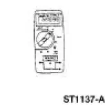
73III Automotive Meter 105-R0057 or equivalent |
 |
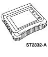
Worldwide Diagnostic System (WDS) 418-F224, New Generation STAR (NGS) Tester 418-F048, or equivalent diagnostic tool |
 Warning Devices
Warning Devices
The warning device system consists of the following components:
door ajar switches
generic electronic module (GEM)
key-in-ignition warning switch
safety belt switch
...
 Principles of Operation
Key-In-Ignition Warning Chime
The key-in-ignition warning chime activates when the generic
electronic module (GEM) detects the
ignition switch circuits are in the OFF or ACC states and when the ...
Other materials:
Muffler - 4.6L (4V)
Removal and Installation
1. Raise and support the vehicle. For additional information, refer to
Section.
2. NOTE: RH side shown, LH side similar.
Remove the dual converter assembly nuts.
3. Remove the RH exhaust hanger insulator (5260).
4. Remove the LH ...
Transmission Drive Cycle Test
NOTE: Always drive the vehicle in a safe manner according to driving
conditions and obey all traffic
laws.
NOTE: The Transmission Drive Cycle Test must be followed exactly.
Malfunctions must occur four
times consecutively for shift error DTC code to be set, ...
Universal Garage Door Opener (If Equipped)
UNIVERSAL GARAGE DOOR OPENER
The appearance of your vehicleâs universal garage door opener will
vary according to your option package. Before programing, make sure
you identify which transmitter you have by comparing it to the graphics
below.
HomeLinkÂź
Ca ...
