Ford Mustang (2005-2014) Owners Manual: Rear-view camera system
WARNING: The rear view camera system is a reverse aid supplement device that still requires the driver to use it in conjunction with the interior and exterior mirrors for maximum coverage.
WARNING: Objects that are close to either corner of the bumper or under the bumper, might not be seen on the screen due to the limited coverage of the camera system.
WARNING: Back up as slow as possible since higher speeds might limit your reaction time to stop the vehicle.
WARNING: Use caution when using the rear video camera and the trunk is ajar. If the trunk is ajar, the camera will be out of position and the video image may be incorrect. All guidelines (if enabled) have been removed when the trunk is ajar.
WARNING: Use caution when turning camera features on or off while the transmission is in R. Make sure the vehicle is not moving.
The rear view camera system provides a video image of the area behind the vehicle.
During operation, lines appear in the display which represent your vehicle’s path and proximity to objects behind the vehicle.

The camera is located on the trunk.
Using the Rear View Camera System
The rear view camera system displays what is behind your vehicle when you place the transmission in R. The system uses fixed guidelines which show the actual path the vehicle is moving in while reversing in a straight line. This can be helpful when backing into a parking space or aligning the vehicle with another object behind the vehicle.
Note: Do not use the camera system if the trunk is ajar.
Note: If the image comes on while the transmission is not in R, have the system inspected by your authorized dealer.
Note: When towing, the camera only sees what is being towed behind the vehicle. This might not provide adequate coverage as it usually provides in normal operation and some objects might not be seen.
In some vehicles, the guidelines may disappear once the trailer tow connector is engaged.
Note: The camera may not operate correctly under the following conditions:
• Nighttime or dark areas if one or both reverse lamps are not
operating.
• The camera’s view is obstructed by mud, water or debris. Clean the
lens with a soft, lint-free cloth and non-abrasive cleaner.
• The rear of the vehicle is hit or damaged, causing the camera to
become misaligned.
Guidelines
Note: The guidelines are only available when the transmission is in R.

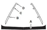
A. Rear bumper
B. Fixed guideline: Red zone
C. Fixed guideline: Yellow zone
D. Fixed guideline: Green zone
The fixed guidelines fade in and out depending on the steering wheel position.
Always use caution while reversing. Objects in the red zone are closest to your vehicle and objects in the green zone are further away. Objects are getting closer to your vehicle as they move from the green zone to the yellow or red zones. Use the side view mirrors and rear view mirror to get better coverage on both sides and rear of the vehicle.
Rear Camera Delay
On vehicles without a navigation system, the camera image in the rear view mirror remains on for a few seconds to assist in parking or attaching a trailer.
On vehicles with a navigation system, the camera image remains in the display until the vehicle speed reaches 5 mph (8 km/h). This occurs when the rear camera delay feature is on, or until a radio button is selected. Selectable settings for this feature are ON and OFF. The default setting for the rear camera delay is OFF.
 Sensing system
WARNING: To help avoid personal injury, please read and
understand the limitations of the system as contained in this
section. Sensing is only an aid for some (generally large and fixed)
objects when ...
 Cruise Control
PRINCIPLES OF OPERATION
Cruise control lets you maintain a set speed without keeping your foot
on the accelerator pedal.
USING CRUISE CONTROL
WARNING: Do not use cruise control in heavy traffic, on
w ...
Other materials:
Accessory Drive
General Specifications
Item
Specification
Accessory drive belt
6 ribs
Supercharger drive belt
8 ribs
Torque Specifications
...
Rear Ride Height Measurement - GT and Base
Item
Description
1
Body reinforcement
2
Ride height (shortest distance)
3
Rear axle
Wheel Track
Item
Part Number
Description
1
-
Front track
2
-
Rear track
Dogtracking
Item
Part N ...
Bezel
Removal
1. Remove the shifter top control panel.
2. Disconnect the electrical connectors.
3. Remove the shifter bezel.
4. Remove the bulb from the bezel.
5. Disconnect the connector.
6. CAUTION: Extra force may be needed to lift up on the handle. Do not ...
