Ford Mustang (1999-2004) Service Manual: Removal
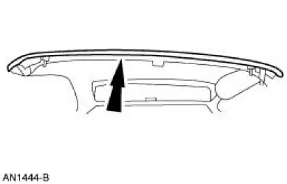
1. Remove the rear exterior trim mouldings.
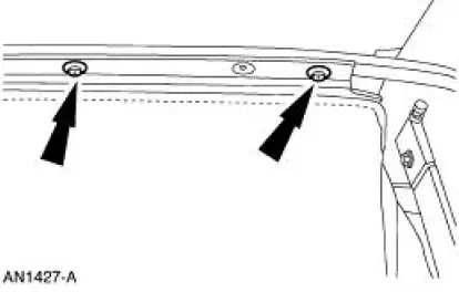
2. Remove the clips
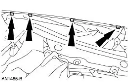
3. Remove the 13 Torx screws and the seal compression panel.
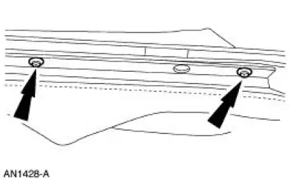
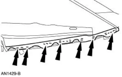
4. Remove the staples.
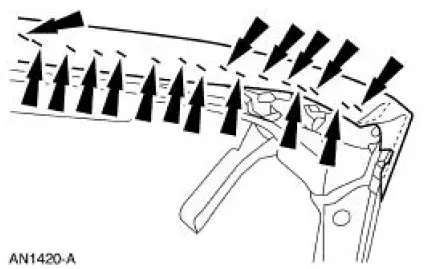
5. Remove the staples from the number one bow.
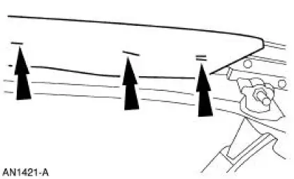
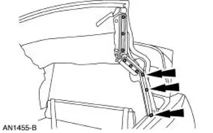
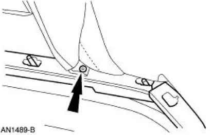
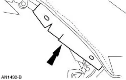
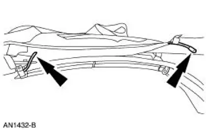
6. Remove the rear rail weatherstrip retainers from each side.
7. Raise the front of the folding top assembly.
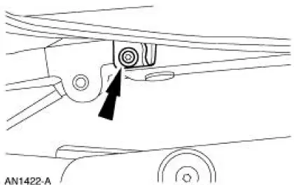
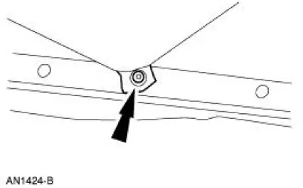
8. Remove the screw and the center elastic straps.
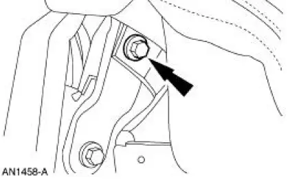
9. Remove the speed nut and the front elastic straps.
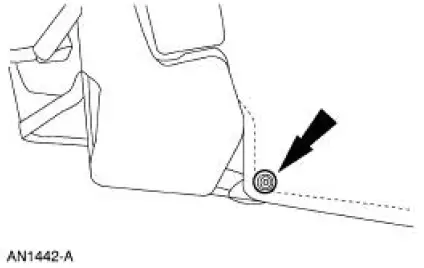
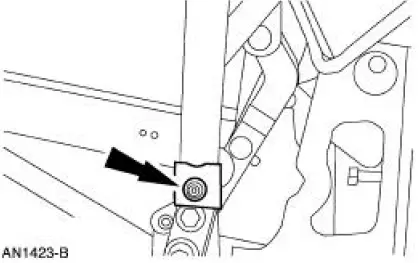
10. Remove the screw and the front elastic strap.
11. Remove the screw and the rear elastic straps.
12. Remove the screw and the rear elastic straps.
13. NOTE: Install new plastic roof headlining retaining pins if they were removed.
Disengage the roof headlining from the folding roof rear side rail.
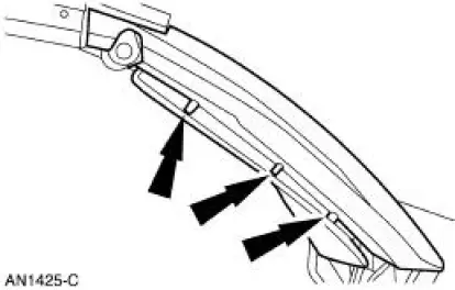
14. Remove the screws from the number four bow.
15. Remove the screws from the number three bow.
16. Remove the screws from the number two bow.
17. Remove the headlining.
18. Remove the nuts retaining the well sling and convertible top tacking strips.
19. Remove screws and the three tacking strips.
20. Remove the staples.
21. NOTE: All adhesive tape must be removed from the folding roof rear side rail.
Pull the roof outside cover flaps to disengage from each folding roof rear side rail.
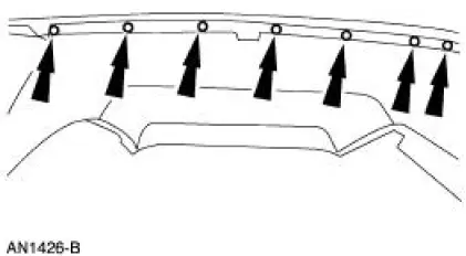
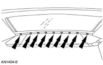
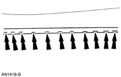
22. Remove the staples from the entire length of the number four bow.
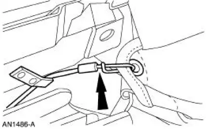
23. Disengage the cable from each side.
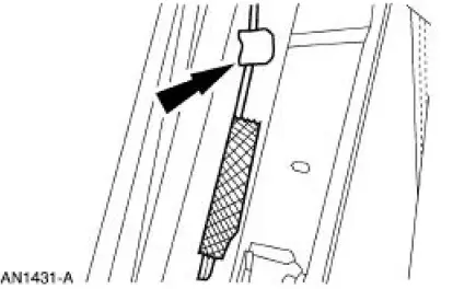
24. Remove the cable from the cover assembly.
25. NOTE: The cable is spring-loaded. Use care not to lose the cable end during disassembly.
Disconnect the trim tension cable.
26. Remove the cover from the frame.

 Installation
1. Align the center mark on the cover assembly to the V-notch on the rear
glass assembly and
staple the entire length of the number four bow.
2. Center the listing sleeve on the bottom of the foldi ...
Other materials:
Rear seats
Rear Seat Entry and Exit
Use the seatback release to fold the
back of the front seat forward for
rear seat access. This release handle
is located on the upper back of the
front seat. The seatback locks
automatically when returned to the
normal position.
Use ...
Using MyKey with remote start systems
MyKey is not compatible with non-Ford-approved aftermarket remote
start systems. If you choose to install a remote start system, please see
your Ford authorized dealer for a Ford-approved remote start system.
Vehicles With Ford-approved Aftermarket Remote Sta ...
Installation
1. Position the fuel charging wiring in the vehicle and attach to the rear of
the intake manifold.
2. NOTE: Make sure the locking clips are fully engaged into the bracket.
Reposition the accelerator cable and the speed control cable (if equipped)
and ...
