Ford Mustang (1999-2004) Service Manual: Connecting Rod - Side Clearance
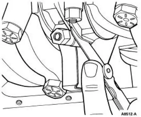
1. Measure the clearance between the connecting rod and the crankshaft. Verify the measurement is within specification.
- Refer to the appropriate section in Group for the procedure.
- If out of specification, install new components as necessary. Refer to the appropriate section in Group for the procedure.
Roller Follower -Inspection
Push rod engines
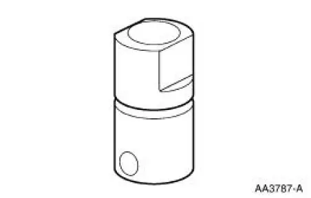
1. Inspect the roller for flat spots or scoring. If any damage is found, inspect the camshaft lobes and valve tappet for damage.

OHC engines
Valve Tappet -Inspection
Push rod engines
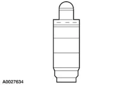
1. Inspect the hydraulic valve tappet and roller for damage. If any damage is found, inspect the camshaft lobes and valves for damage.
OHC engines
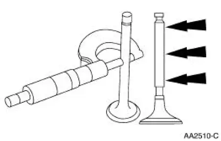
Valve -Stem Diameter
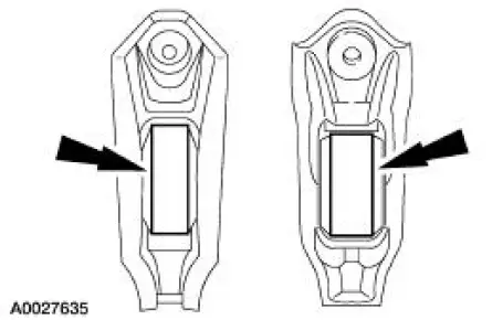
1. Measure the diameter of each intake and exhaust valve stem at the points shown. Verify the diameter is within specification.
- Refer to the appropriate section in Group for the procedure.
- If out of specification, install new components as necessary. Refer to the appropriate section in Group for the procedure.
 Connecting Rod - Bearing Journal Clearance
Special Tool(s)
Plastigage
303-D031 (D81L-6002-B) or
equivalent
NOTE: The crankshaft connecting rod journals must be within
specifications to check the connecting
rod bearing journa ...
 Valve Stem to Valve Guide Clearance
Special Tool(s)
Dial Indicator Gauge with
Holding Fixture
100-002 (TOOL-4201-C) or
equivalent
Clearance Gauge, Valve Guide
303-004 (TOOL-6505-E) or
equivalent
NOTE: Valve ...
Other materials:
Spring Lock Couplings
Special Tool(s)
Disconnect Tool, Spring Lock
Coupling (3/8 inch yellow)
310-D004 (D87L-9280-A) or
equivalent
Disconnect Tool, Spring Lock
Coupling (1/2 inch green)
310-D005 (D87L-9280-B) or
equivalent
Material
Item
...
Removal
1. Remove the air intake scoop bracket. For additonal information, refer to
Section.
2. Remove the air cleaner outlet tube. For additional information, refer to
Section.
3. Disconnect the accelerator cable, the speed control actuator cable and the
return ...
Wheel Knuckle - Cobra
Special Tool(s)
Front Hub Remover
205-D070 (D93P-1175-B) or
Equivalent
Steering Arm Remover
211-003 (T64P-9171-A)
...
