Ford Mustang (1999-2004) Service Manual: Removal
WARNING: The restraints control module (RCM) orientation is critical for proper system operation. If a vehicle equipped with an air bag supplemental restraint system (SRS) has been involved in a collision in which the center tunnel area has been damaged, inspect the mounting and bracket for deformation. If damaged, the RCM must be replaced whether or not the air bags have deployed. In addition, make sure the area of the RCM mounting is restored to its original condition.
WARNING: Vehicle sensor orientation is critical for proper system operation. If a vehicle equipped with an air bag supplemental restraint system (SRS) is involved in a collision, inspect the sensor mounting bracket and wiring pigtail for deformation. Replace and properly position the sensor or any other damaged supplemental restraint system (SRS) components whether or not the air bag is deployed.
WARNING: The restraint system diagnostic tool is for restraint system service only.
Remove from vehicle prior to road use. Failure to remove could result in injury and possible violation of vehicle safety standards.
CAUTION: Electronic modules are sensitive to static electrical charges. If exposed to these charges, damage can result.
NOTE: Repair is made by installing a new part only. If the new part does not correct the condition, install the original part and perform the diagnostic procedure again.
1. Prepare the vehicle for restraints control module (RCM) removal.
1. WARNING: To avoid accidental deployment and possible personal injury, the backup power supply must be depleted before repairing or replacing any front or side air bag supplemental restraint system (SRS) components and before servicing, replacing, adjusting or striking components near the front or side air bag sensors, such as doors, instrument panel, console, door latches, strikers, seats and hood latches.
Please refer to the appropriate vehicle shop manual to determine location of the front air bag sensors.
The side air bag sensors are located at or near the base of the B-pillar.
To deplete the backup power supply energy, disconnect the battery ground cable and wait at least one minute. Be sure to disconnect auxiliary batteries and power supplies (if equipped).
Disconnect the battery ground cable (14301) and wait at least one minute. For additional information, refer to Section.
2. WARNING: To reduce the risk of serious personal injury, read and follow all warnings, cautions, notes, and instructions in the supplemental restraint system (SRS) deactivation/reactivation procedure.
Deactivate the supplemental restraint system (SRS). For additional information, refer to Supplemental Restraint System (SRS) Deactivation and Reactivation in the General Procedures portion of this section.
2. Remove the right hand restraints control module (RCM) bracket retaining bolt.
1. Position the carpet back at the right hand side of the instrument panel (I/P) center support bracket.
2. Remove the RCM bracket retaining bolt.
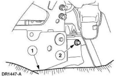
3. Remove the RCM with bracket.
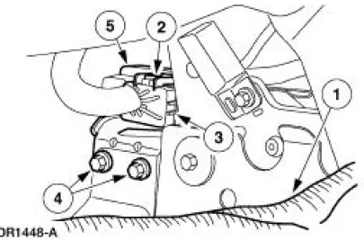
1. Position the carpet back at the left hand side of the I/P center support bracket.
2. Disengage the RCM electrical connector locking clip.
3. Disconnect the RCM electrical connector.
4. Remove the two retaining bolts.
5. Remove the RCM with bracket.
 Restraints Control Module (RCM)
Special Tool(s)
Diagnostic Tool, Restraint
System (2 Req'd)
418-F088 (105-R0012)
...
 Installation
WARNING: To reduce the risk of serious personal injury, read
and follow all warnings,
cautions and notes at the beginning of the removal procedure.
1. WARNING: The tightening torque of the air ...
Other materials:
Removal
All vehicles
1. Remove the air intake scoop. For additional information, refer to Section.
2. Remove the Hydro-Boost brake booster. For additional information, refer to
Section..
3. Raise and support the vehicle. For additional information, refer to Section ...
Range Selection
The transmission has six range positions: P, R, N, (D), 2 and 1.
Park
In the PARK position:
there is no powerflow through the transmission.
the parking pawl locks the output shaft to the case.
the engine can be started.
the ignition key can ...
Torque Converter Diagnosis
Prior to the installation of a new or remanufactured torque
converter, all diagnostic procedures must be
followed. This is to prevent the unnecessary installation of torque
converters. Only after a complete
diagnostic evaluation can the decision be m ...
