Ford Mustang (1999-2004) Service Manual: Sprockets
1. WARNING: To avoid the possibility of personal injury or damage to the vehicle, do not operate the engine with the hood open until the fan blade has been examined for possible cracks and separation.
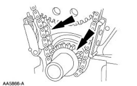
NOTE: Specifications show the expected minimum or maximum condition. Refer to the appropriate section in Group 303 for the procedure.
NOTE: If a component fails to meet the specifications, it is necessary to install a new component or refinish. If the component can be refinished, wear limits are provided as an aid to making a decision. A new component must be installed for any component that fails to meet specifications and cannot be refinished.
Inspect the timing chain/belt and the sprockets.
- Install new components as necessary. Refer to the appropriate section in Group 303 for the procedure.
Rocker Arms - Cleaning
1. Clean all parts thoroughly. Make sure all oil passages are open.
2. Make sure oil passage in the push rod/valve tappet end of the rocker arm (6564) is open.
 Component Tests
Engine Oil Leaks
NOTE: When diagnosing engine oil leaks, the source and location of
the leak must be positively
identified prior to repair.
Prior to carrying out this procedure, clean all sealin ...
 Rocker Arms - Inspection
CAUTION: Do not attempt to true surfaces by grinding. Check the
rocker arm pad, side
rails and seat for excessive wear, cracks, nicks or burrs. Check the rocker
arm seat bolt for
stripped or bro ...
Other materials:
Engine Ignition (Description and Operation)
Eight separate ignition coils:
are controlled by the powertrain control module (PCM).
are mounted directly above each spark plug.
are controlled by the powertrain control module for correct firing
sequence.
The spark plug:
changes the high vo ...
Starter Motor - 3.8L
Removal
WARNING: When servicing starter motor (11002) or carrying out other
underhood work in
the vicinity of the starter motor, be aware that the heavy gauge battery
input lead at the starter
solenoid (11390) is "electrically hot" at all times. A prote ...
Transmission Electronic Control System
The powertrain control module (PCM) and its input/output network
control the following transmission
operations:
Shift timing
Line pressure (shift feel)
Torque converter clutch
The transmission control is separate from the engine control s ...
