Ford Mustang (1999-2004) Service Manual: Engine System - General Information
General Specifications
Engine
NOTE: This section contains information, steps and procedures that may not be specific to your engine.
This section covers general procedures and diagnosis and testing of the engine system, except for exhaust emission control devices, which are covered in the Powertrain Control/Emissions Diagnosis Manual.
The engine incorporates the following features:
- a closed positive crankcase ventilation (PCV) system.
- an exhaust emission control system.
- an evaporative emission control system.
Some engines incorporate a fail-safe cooling system. Refer to the appropriate section in Group for the procedure.
The engine, fuel system, ignition system, emissions system and exhaust system all affect exhaust emission levels and must be maintained according to the maintenance schedule. Refer to the scheduled Maintenance Guide.
Correct engine identification is required to order parts. Refer to the appropriate section in Group for the procedure.
For complete vehicle and engine identification codes.
- Engine (Diagnosis and Testing)
- Sprockets
- Rocker Arms - Inspection
- Push Rods - Inspection
- Camshaft Journal - Clearance, Plastigage Method
- Camshaft End Play - Push Rod Engines
- Camshaft End Play - OHC Engines
- Camshaft Lobe Lift
- Camshaft Runout
- Crankshaft Main Bearing Journal - Clearance
- Crankshaft End Play
- Crankshaft Runout
- Crankshaft - Connecting Rod Journal Taper, Out of Round
- Piston Inspection
- Piston - Pin to Bore Diameter
- Piston - Selection
- Piston - Ring End Gap
- Piston - Ring-to-Groove Clearance
- Piston - Pin Diameter
- Connecting Rod - Bushing Diameter
- Connecting Rod - Twist
- Connecting Rod - Bearing Journal Clearance
- Connecting Rod - Side Clearance
- Valve Stem to Valve Guide Clearance
- Valve Spring Strength
- Valve - Seat Inspection
- Cylinder Head - Distortion
- Cylinder Block Core Plug Replacement
- Spark Plug - Inspection
- Exhaust Manifold - Inspection
 Engine
...
 Engine (Diagnosis and Testing)
Special Tool(s)
Commercially Available
Leakdown Tester
Quick Disconnect Compression
Tester
134-R0212 or equivalent
Dial Indicator Gauge Adapter
303-007 (TOOL-6565-AB) ...
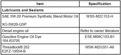
Other materials:
Headlamp Adjustment
Headlamp Aiming
1. The headlamp aiming procedure depends on the type of beam pattern the
headlamp is
equipped with. Vehicles may come equipped with visual optical right (VOR),
visual optical left
(VOL), or SAE only (includes sealed beam type) headlamps. ...
Removal
1. Remove the nuts and position the radio ignition interference capacitors
aside.
2. Remove the valve covers. For additional information, refer to Valve Cover
RH and Valve Cover
LH in this section.
3. Remove the cooling fan.
4. Remove the accessory drive ...
Disassembly
1. Remove the differential assembly from the differential housing. For
additional information, refer
to Differential Case in this section.
2. Remove the bolts.
3. CAUTION: Do not damage the threads in the bolt holes.
Insert a punch in the bolt holes and d ...
