Ford Mustang (1999-2004) Service Manual: Switch - Speed Control Actuator
Removal
1. Remove the steering wheel; refer to Section.
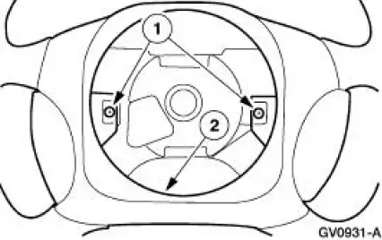
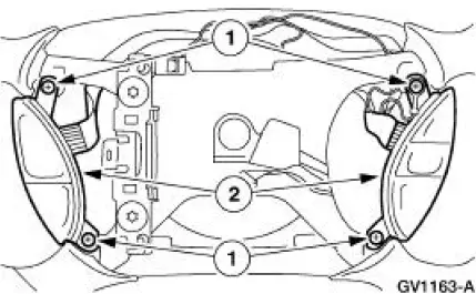
2. Remove the steering wheel rear cover.
1. Remove the screws.
2. Remove the steering wheel rear cover.
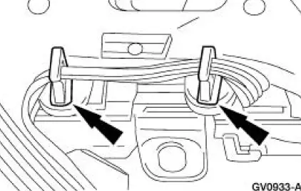
3. Remove the ribbon harness from the clips.
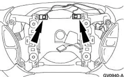
4. Remove the horn contact electrical connectors.
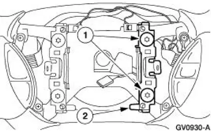
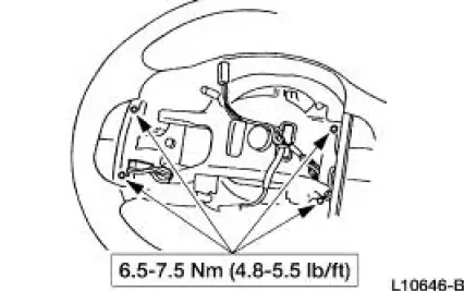
5. Remove the right side horn contact.
1. Remove the screws.
2. Remove the contact.
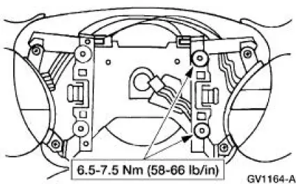
6. Remove the speed control actuator switch assembly.
1. Remove the screws.
2. Remove the speed control actuator switch assembly.
Installation
1. To install, reverse the removal procedure.
 Switch - Deactivator
Removal
1. Disconnect the battery ground cable.
2. Remove the deactivator switch.
1. Disconnect the deactivator switch electrical connector.
2. Detach the lower deactivator switch hook.
3 ...

Other materials:
Lead Terminal Repair
Special Tool(s)
Heat Gun
107-R0300 or equivalent
Material
Item
Specification
Rear Window Defroster Repair
D8AZ-19562-AA
WSB-M4J58-B
1. NOTE: The rear window glass must be at room temperature at the time of the
repair.
Clea ...
Ordering additional owner’s literature
To order the publications in this portfolio, contact Helm, Incorporated at:
HELM, INCORPORATED
47911 Halyard Drive
Plymouth, Michigan 48170
Attention: Customer Service
Or to order a free publication catalog, call toll free: 1-800-782-4356
Monday-Friday 8:00 a. ...
Suction Accumulator
NOTE: Installation of a new suction accumulator is not required when
repairing the air conditioning
system except when there is physical evidence of contamination from a failed A/C
compressor or
damage to the suction accumulator.
In addition to th ...
