Ford Mustang (1999-2004) Service Manual: Connecting Rod - Side Clearance
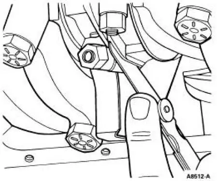
1. Measure the clearance between the connecting rod and the crankshaft. Verify the measurement is within specification.
- Refer to the appropriate section in Group for the procedure.
- If out of specification, install new components as necessary. Refer to the appropriate section in Group for the procedure.
Roller Follower -Inspection
Push rod engines
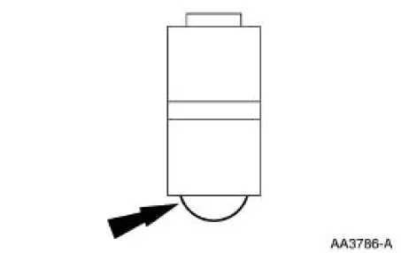
1. Inspect the roller for flat spots or scoring. If any damage is found, inspect the camshaft lobes and valve tappet for damage.
OHC engines
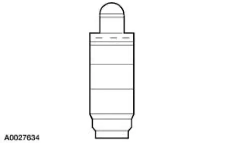
Valve Tappet -Inspection
Push rod engines
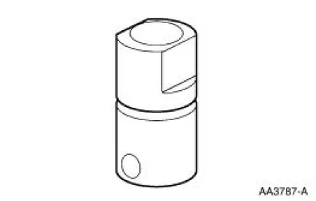
1. Inspect the hydraulic valve tappet and roller for damage. If any damage is found, inspect the camshaft lobes and valves for damage.
OHC engines
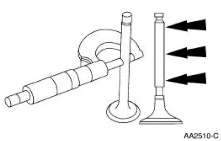
Valve -Stem Diameter
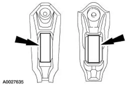
1. Measure the diameter of each intake and exhaust valve stem at the points shown. Verify the diameter is within specification.
- Refer to the appropriate section in Group for the procedure.
- If out of specification, install new components as necessary. Refer to the appropriate section in Group for the procedure.
 Connecting Rod - Bearing Journal Clearance
Special Tool(s)
Plastigage
303-D031 (D81L-6002-B) or
equivalent
NOTE: The crankshaft connecting rod journals must be within
specifications to check the connecting
rod bearing journa ...
 Valve Stem to Valve Guide Clearance
Special Tool(s)
Dial Indicator Gauge with
Holding Fixture
100-002 (TOOL-4201-C) or
equivalent
Clearance Gauge, Valve Guide
303-004 (TOOL-6505-E) or
equivalent
NOTE: Valve ...
Other materials:
Water Pump - 3.8L
Material
Item
Specification
Motorcraft Premium Gold
Engine Coolant
VC-7-A (in Oregon VC-7-B)
(yellow color)
WSS-M97B51-
A1
Removal and Installation
1. Drain the engine coolant. For additional information, refer to Cooling
System Dra ...
Accessory Drive Belt Idler Pulley - 4.6L (2V) and (4V)
Removal and Installation
Mach I
1. Remove the air intake scoop. For additional information, refer to Section.
Cobra
2. Remove the supercharger drive belt cover.
3. Rotate the supercharger belt tensioner clockwise and remove the
supercharger belt.
4. Remov ...
Reverse Clutch
Special Tool(s)
Dial Indicator Gauge with
Holding Fixture
100-002 (TOOL-4201-C)
Compressor, Clutch Spring
307-015 (T65L-77515-A)
Protector, Transmission
Reverse Clutch Outer Fluid
Seal
307-424
Protecto ...
