Ford Mustang (1999-2004) Service Manual: Engine (Removal)
Special Tool(s)
|
|
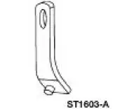
Lifting Bracket, Engine 303-D087 (D93P-6001-A1) |
 |
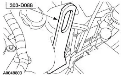
Lifting Bracket, Engine 303-D088 (D93P-6001-A2) |
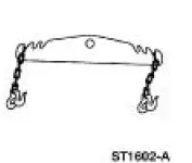 |
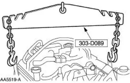
Spreader Bar 303-D089 (D93P-6001-A3) |
Removal
All vehicles
1. Disconnect the battery ground cable. For additional information, refer to Section.
2. Remove the hood-to-body ground strap.
3. NOTE: Mark the hood hinge locations to aid in hood installation.
Remove the four nuts and the hood.
4. Recover the A/C system. For additional information, refer to Section.
5. Remove the air intake scoop bracket. For additional information, refer to Section.
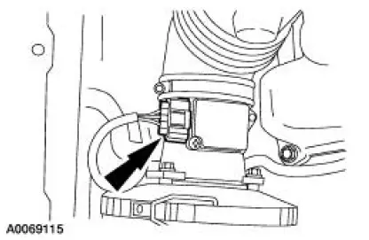
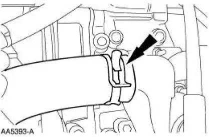
6. Disconnect the air cleaner outlet pipe at the throttle body.
1. Disconnect the positive crankcase ventilation (PCV) inlet tube.
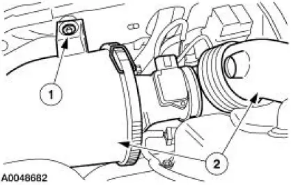
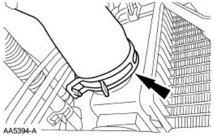
2. Loosen the clamp and disconnect the outlet pipe.
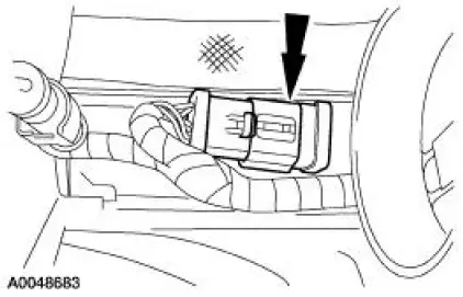
7. Disconnect the mass airflow sensor electrical connector.
8. Remove the air cleaner.
1. Remove the bolt.
2. Remove the air cleaner and the outlet pipe as an assembly.
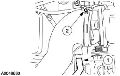
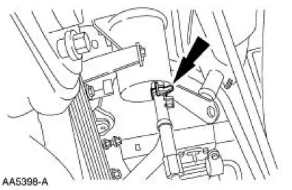
9. Disconnect the electrical connector.
10. Drain the engine cooling system. For additional information, refer to Section.
11. Disconnect the fuel tube spring lock coupling. For additional information, refer to Section.
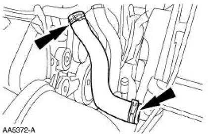
12. Remove the upper radiator hose (8260).
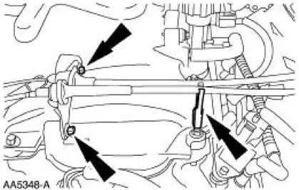
13. Disconnect the throttle cable, and the speed control cable, and remove the throttle return spring.
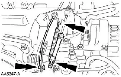
14. Remove the bolts and detach the retainer. Position the cables and the bracket aside.
15. Disconnect the evaporative emissions return line.
16. Disconnect the 16-pin and the 42-pin connectors.
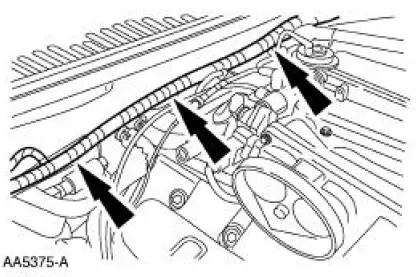
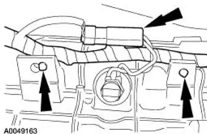
17. Separate the engine control sensor wiring in three locations and position onto the engine.
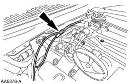
18. Disconnect the vacuum hoses.
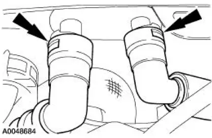
19. Disconnect the heater hoses.
20. Remove the wiring support bracket.
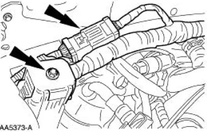
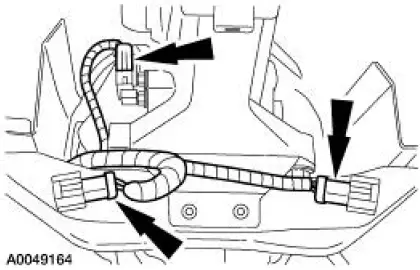
21. Disconnect the connectors.
22. Raise the cover and remove the nut and cables.
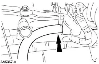
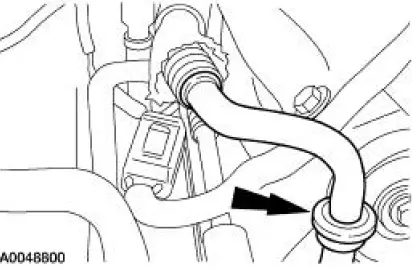
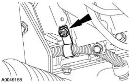
23. Disconnect the hose from the coolant bypass tube.
24. Disconnect the A/C suction tube from the accumulator.
25. Disconnect and remove the A/C suction tube.
26. Disconnect the A/C tube. Position A/C tube aside.
27. NOTE: The lifting bracket bolts will be installed when the vehicle is raised.
Position the RH lifting bracket.
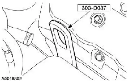
28. Install the LH lifting bracket.
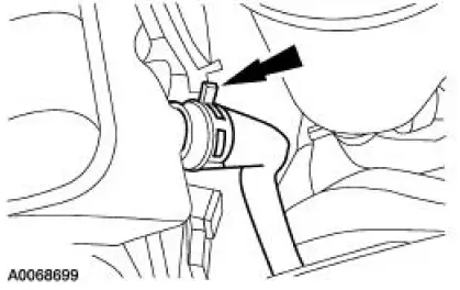
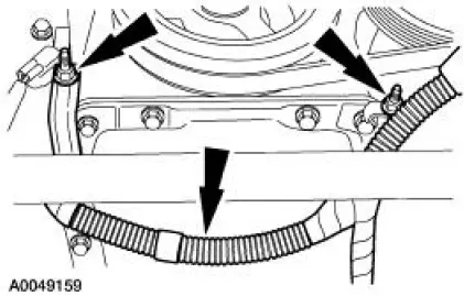
29. Disconnect the radiator vent hose from the degas bottle.
30. Remove the degas bottle return hose.
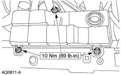
31. Remove the nuts and the degas bottle
32. Remove the shifter.
33. Remove the dual converter H-pipe.
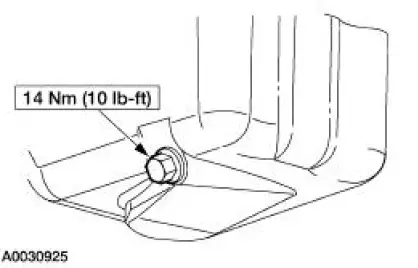
34. Drain the engine oil.
- Install the drain plug when finished.
35. Position the A/C muffler aside.
1. Remove the bracket retainer.
2. Disconnect the A/C tube and position the A/C muffler aside.
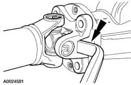
36. Index-mark the driveshaft flange and the rear axle pinion flange.
37. Remove the four bolts
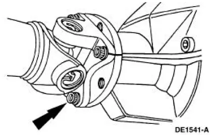
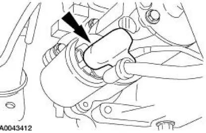
38. Index-mark the driveshaft at the six o'clock position.
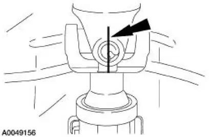
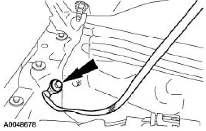
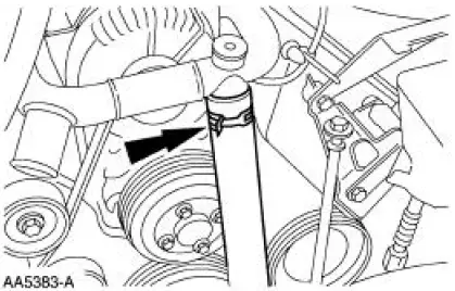
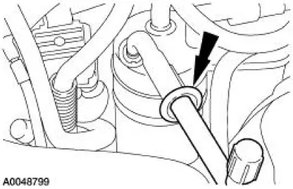
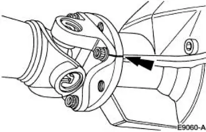
39. CAUTION: the driveshaft flange fits tightly on the rear axle pinion flange pilot. Never hammer on the driveshaft or any of its components to disconnect the driveshaft flange from the pinion flange. Pry only in the area shown, with a suitable tool, to disconnect the driveshaft flange from the pinion flange.
NOTE: Do not rotate the driveshaft.
Using a suitable tool, disconnect the driveshaft flange from the rear axle flange and remove the driveshaft.
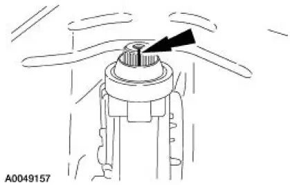
40. Index-mark the transmission output shaft at the six o'clock position.
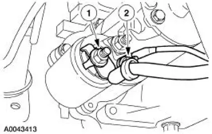
41. Remove the starter motor terminal cover.
42. Disconnect the starter wiring.
1. Remove the nut and disconnect the battery positive cable.
2. Remove the nut and disconnect the starter solenoid wire.
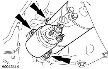
43. Remove the three bolts and the starter.
Automatic transmission vehicles
44. Remove the flywheel inspection cover.
45. Remove the torque converter nuts.
All vehicles
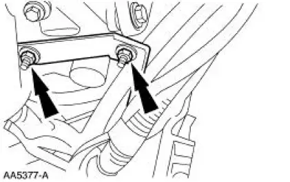
46. Remove the nut and the wiring harness bracket.
47. Remove the nuts and position the wiring harness aside.
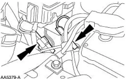
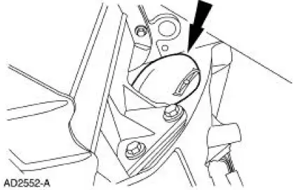
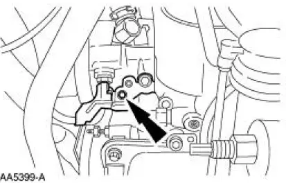
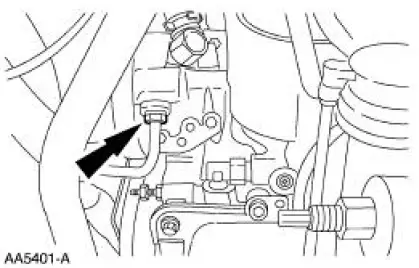
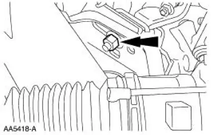
48. Disconnect the oil pressure sensor.
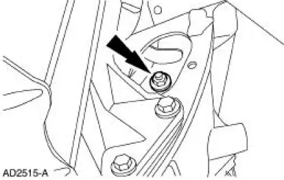
49. Remove the nut and the engine ground cable.
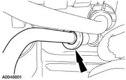
50. Disconnect the hose from the oil filter adapter.
51. Disconnect and remove the lower hose from the radiator.
52. NOTE: Drain the power steering fluid into a suitable container.
Disconnect the hose from the power steering reservoir.
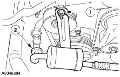
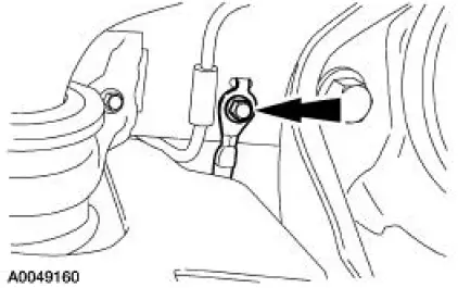
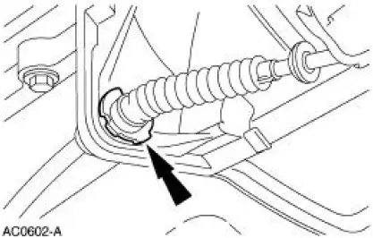
53. Remove the bolt and the anti-rotation clip.
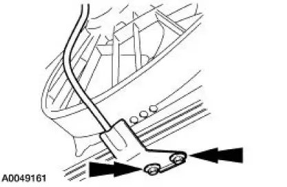
54. Loosen the fitting and disconnect the high pressure hose from the power steering pump.
55. Remove the ground strap bolt.
56. Remove the degas bottle support bracket.
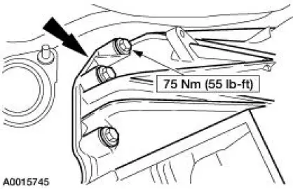
57. Install the two bolts from the RH lifting bracket.
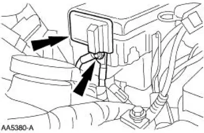
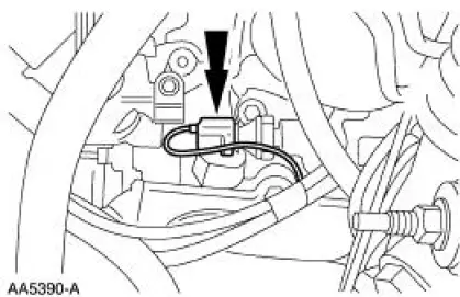
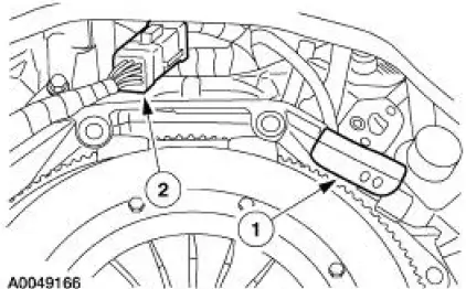
58. Disconnect the reversing lamp switch electrical connector, and the wiring harness from the transmission.
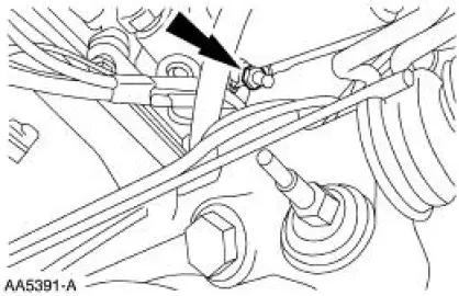
59. Disconnect the output shaft speed (OSS) sensor electrical connector and detach the left and right oxygen sensor electrical connectors from the crossmember.
Manual transmission vehicles
60. Remove the bolt and the clutch release lever cover.
61. CAUTION: To prevent component damage, do not depress the clutch pedal with the transmission removed.
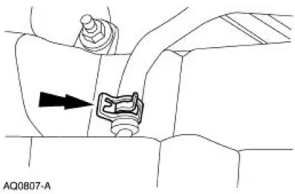
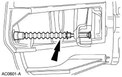
Detach the clutch release cable from the clutch release fork.
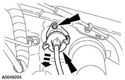
62. Remove the clutch cable retainer and remove the clutch cable from the transmission.
All vehicles
63. Position a transmission jack and support the transmission.
64. Remove the transmission crossmember bolts.
Automatic transmission vehicles
65. Remove the bolts
All vehicles
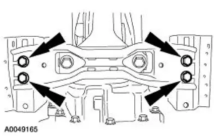
66. Lower the transmission, remove the seven bolts, and remove the transmission.
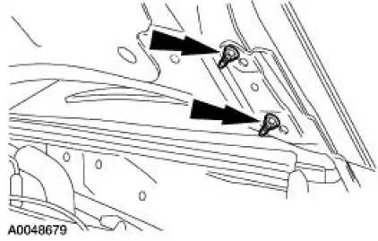
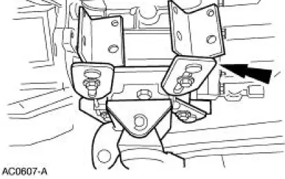
67. NOTE: RH side shown, LH side similar.
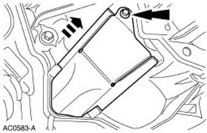
Remove the two engine mount nuts.
68. Remove the transmission wiring harness.
1. Remove the RH oxygen sensor connector from the bracket.
2. Disconnect the transmission wiring connector and remove the harness.
69. Lower the vehicle.
Manual transmission vehicles
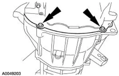
70. Remove the two screws and position the clutch cable aside.
All vehicles
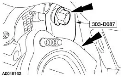
71. Attach the special tool to a floor crane and the engine, and remove the engine from the vehicle.
 Installation
LH mount
1. Position the engine mount and install the bolt and studbolts.
2. Attach the ground cables and install the nuts.
RH mount
3. Position the engine mount and install the bolts and studbolt ...
 Engine (Disassembly)
Special Tool(s)
Impact Slide Hammer
100-001 (T50T-100-A)
Remover, Crankshaft Vibration
Damper
303-009 (T58P-6316-D)
Holding Tool, Crankshaft
303-448 (T93P ...
Other materials:
Engine Cooling (Diagnosis and Testing)
Special Tool(s)
Pressure Tester
014-R1072 or equivalent
73III Automotive Meter
105-R0057 or equivalent
Worldwide Diagnostic System
(WDS)
418-F224,
New Generation STAR (NGS)
Tester
418-F052, or equivalent scan ...
Pinpoint Tests
NOTE: Reinstall or install new evaporative emission hose clamps
removed or damaged during testing
procedures.
PINPOINT TEST A: DTC P0442 SMALL LEAK IN EVAP SYSTEM
Test Step
Result / Action to Take
NOTE: Condition P0442 DTC set: less than 0.62 ...
Forward Clutch Cylinder
Special Tool(s)
Dial Indicator Gauge with
Holding Fixture
100-002 (TOOL-4201-C) or
equivalent
Compressor, Clutch Spring
307-096 (T81P-70235-A)
Protector, Transmission
Forward Clutch Outer Fluid
Seal
307-423
M ...
