Ford Mustang (1999-2004) Service Manual: Installation
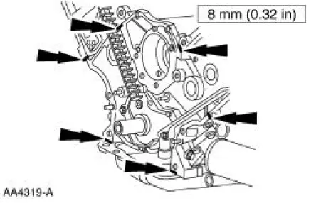
1. Apply silicone gasket and sealant in the locations shown.
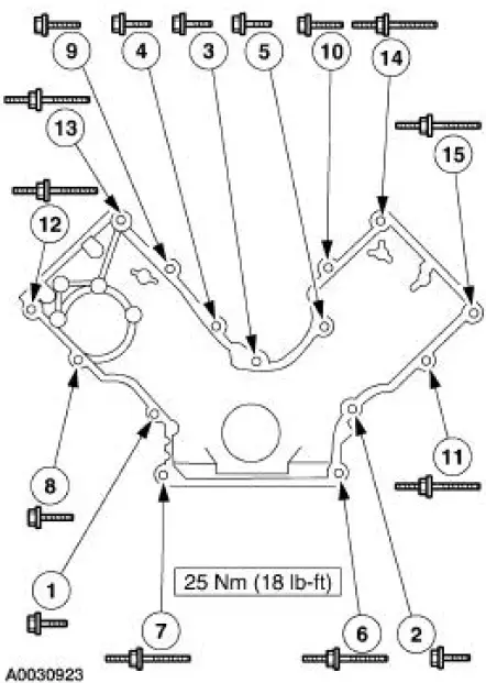
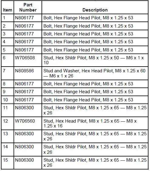
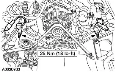
2. Install the engine front cover.
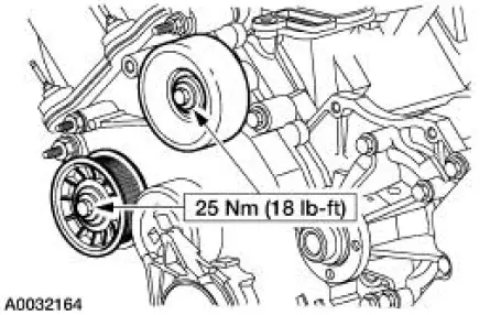
3. Install the belt idler pulleys and the bolts.
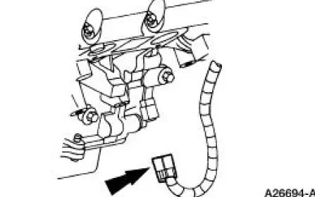
4. Connect the CMP sensor electrical connector.
5. Raise the vehicle.
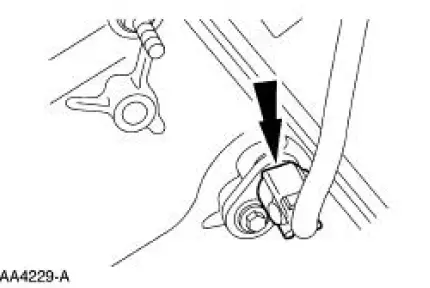
6. Install the crankshaft front oil seal. For additional information, refer to Crankshaft Front Oil Seal in this section.
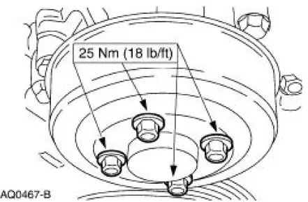
7. Tighten the four oil pan bolts in the sequence shown.
- Stage 1: Tighten to 2 Nm (18 lb-in).
- Stage 2: Tighten to 20 Nm (15 lb-ft).
- Stage 3: Tighten an additional 60 degrees.
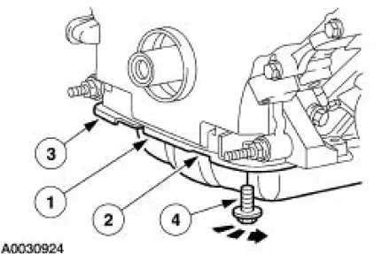
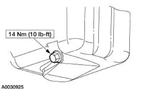
8. Install the drain plug.
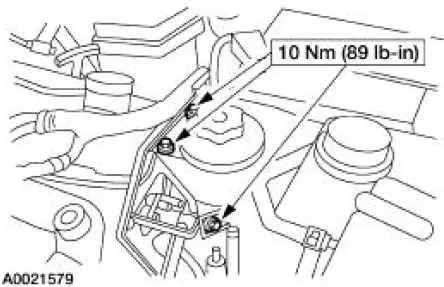
9. Position the power steering reservoir and install the bolts.
10. Connect the CKP sensor electrical connector.
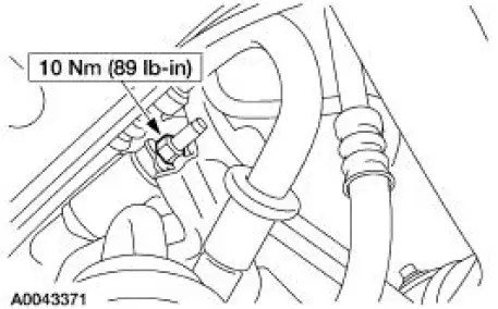
11. Position the A/C muffler and tighten the nut.
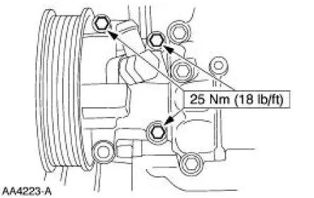
12. Install the power steering pump and the bolts.
13. Position the battery cable and install the two nuts.
14. Install the crankshaft pulley. For additional information, refer to Crankshaft Pulley in this section.
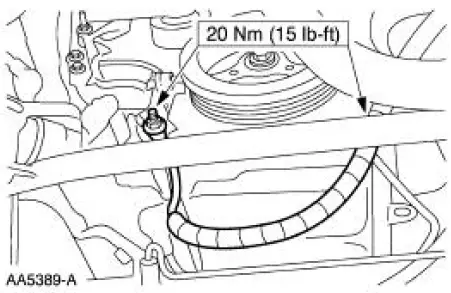
15. Install the water pump pulley and the bolts.
16. Install the cooling fan.
17. Install the accessory drive belt. For additional information, refer to Section
18. Install the valve covers. For additional information, refer to Valve Cover RH and Valve Cover LH in this section.
19. Position the radio ignition interference capacitors and install the nuts.
20. Fill the crankcase with clean engine oil.
 Removal
1. Remove the nuts and position the radio ignition interference capacitors
aside.
2. Remove the valve covers. For additional information, refer to Valve Cover
RH and Valve Cover
LH in this section ...
 Timing Drive Components
Special Tool(s)
Compressor, Valve Spring
303-567 (T97P-6565-AH)
Holding Tool, Crankshaft
303-448 (T93P-6303-A)
Aligner, Camshaft Position
303-557 (T96T-6256-B) ...
Other materials:
Caliper
1. NOTE: It is not necessary to do a complete brake system
bleed if only the disc brake caliper
(2B120) was disconnected.
Place a box end wrench on the disc brake caliper bleeder screw (2208).
Attach a rubber drain
tube to the disc brake caliper b ...
Cleaning the alloy wheels
Note: Do not use chrome cleaner, metal cleaner or polish on wheels and
wheel covers.
A clearcoat paint finish coats aluminum wheels and wheel covers.
In order to maintain their condition:
• Clean weekly with Motorcraft Wheel and Tire Cleaner. Use a sponge ...
Switch - Seat Regulator Control
Removal and Installation
1. Disconnect the battery. For additional information, refer to Section.
2. Remove the screws and position the seat regulator control switch aside.
3. Disconnect the electrical connector and remove the seat regulator control
swit ...
