Ford Mustang (1999-2004) Service Manual: Removal
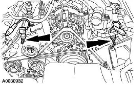
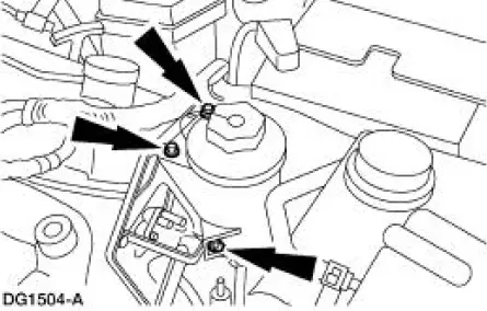
1. Remove the nuts and position the radio ignition interference capacitors aside.
2. Remove the valve covers. For additional information, refer to Valve Cover RH and Valve Cover LH in this section.
3. Remove the cooling fan.
4. Remove the accessory drive belt. For additional information, refer to Section.
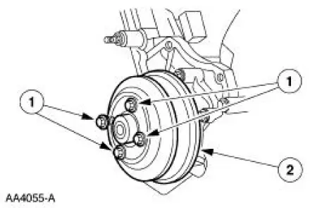
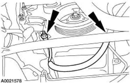
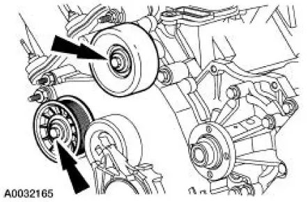
5. Remove bolts (1) and the water pump pulley (2).
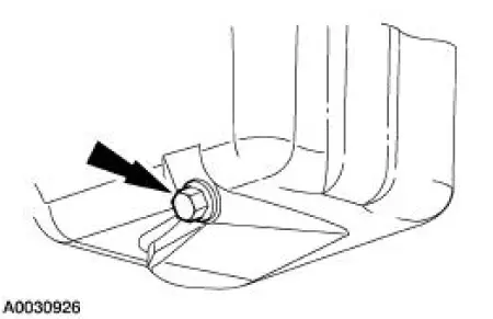
6. Remove the nut and position the A/C muffler aside.
7. Raise and support the vehicle. For additional information, refer to Section.
8. Remove the bolts and position the power steering pump aside.
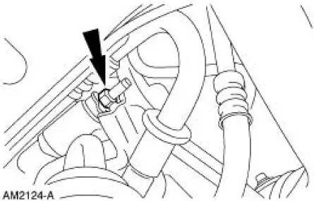
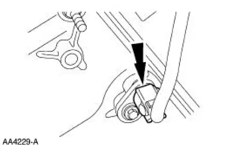
9. Disconnect the crankshaft position (CKP) sensor electrical connector.
10. Drain the engine oil.
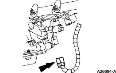
11. Remove the two support nuts and position the battery cable aside.
12. Remove the crankshaft front oil seal. For additional information, refer to Crankshaft Front Oil Seal in this section.
13. Remove the front oil pan bolts.
14. Lower the vehicle.
15. Remove the bolts and position the power steering reservoir aside.
16. Disconnect the camshaft position (CMP) sensor electrical connector.
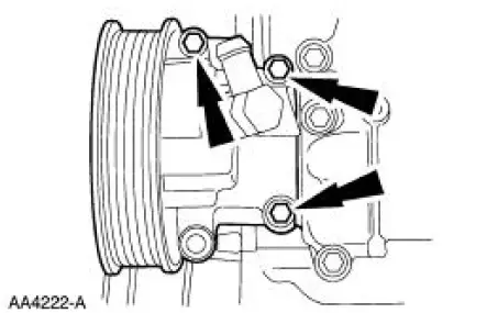
17. Remove the bolts and the belt idler pulleys.
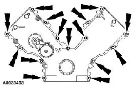
18. Remove the engine front cover bolts and the studs.
- Discard the gaskets. Clean and inspect the sealing surfaces.
 Engine Front Cover
Material
Item
Specification
Silicone Gasket and Sealant
F7AZ-19554-EA or equivalent
WSE-M4G323-
A4
Super Premium SAE 5W-20
Motor Oil
XO-5W20-QSP or equivalent
WSS-M2C153 ...
 Installation
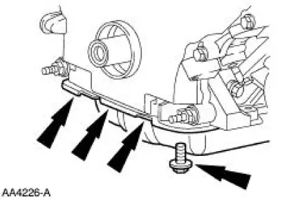
1. Apply silicone gasket and sealant in the locations shown.
2. Install the engine front cover.
3. Install the belt idler pulleys and the bolts.
4. Connect the CMP sensor electrical conn ...
Other materials:
Removal
1. Remove the nuts and position the radio ignition interference capacitors
aside.
2. Remove the valve covers. For additional information, refer to Valve Cover
RH and Valve Cover
LH in this section.
3. Remove the cooling fan.
4. Remove the accessory drive ...
Engine (Installation)
Special Tool(s)
Lifting Bracket, Engine
303-D087 (D93P-6001-A1)
Lifting Bracket, Engine
303-D088 (D93P-6001-A2)
Installer Set, Teflon Seal
211-D027 (D90P-3517A) or
equivalent
Spreader Bar
303-D089 (D9 ...
Removal
CAUTION: Suspension fasteners are critical parts because they affect
performance of vital
components and systems and their failure can result in major service expense. A
new part with
the same part number must be installed if installation becomes necessary. ...
