Ford Mustang (1999-2004) Service Manual: Removal
1. Drain the engine cooling system.
2. Remove the air cleaner outlet tube.
3. Disconnect the fuel line.
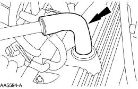
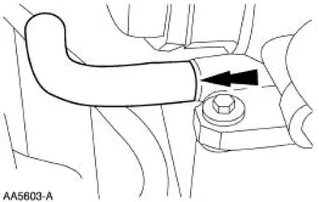
4. Disconnect the upper radiator hose from the water outlet connector.
5. Disconnect and remove the upper radiator hose.
6. Disconnect the accelerator cable, speed control actuator cable and return spring.
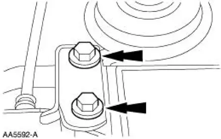
7. Remove the bolts and position the cables and bracket out of the way.
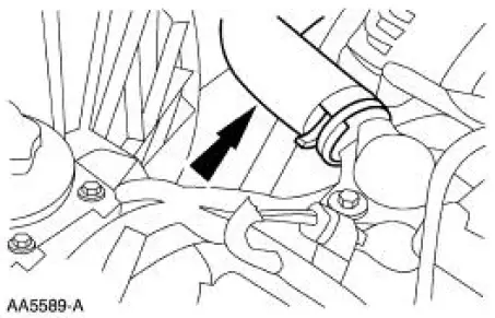
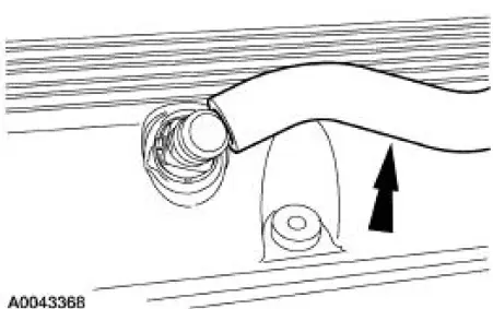
8. Remove the breather tube.
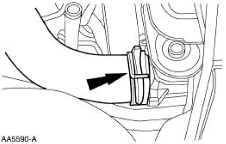
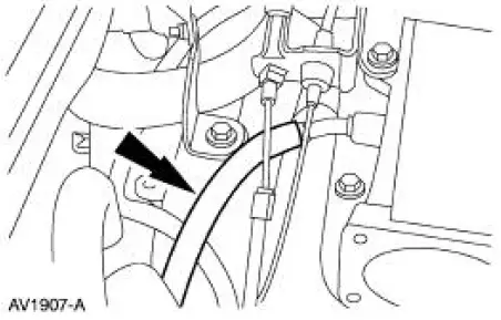
9. Disconnect the evaporative emissions return line.
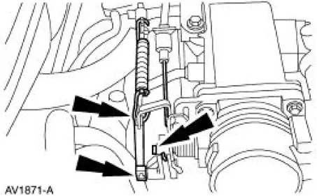
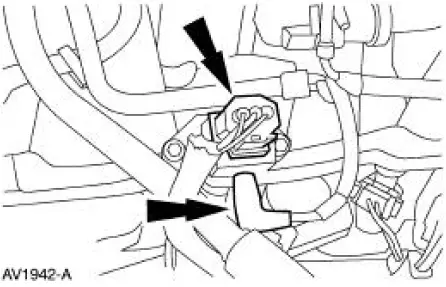
10. Disconnect the differential pressure feedback EGR electrical connector.
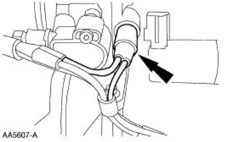
11. Disconnect the hoses from the differential pressure feedback EGR transducer.
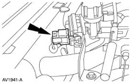
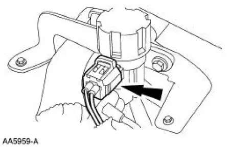
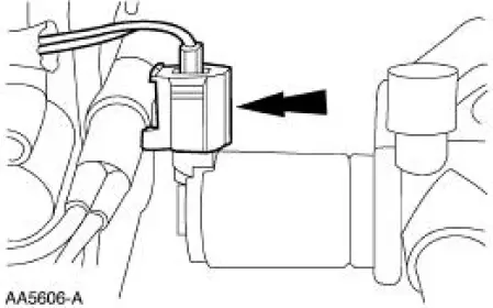
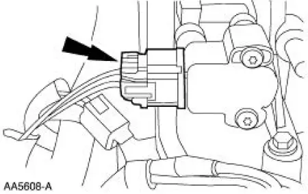
12. Disconnect the EGR vacuum regulator solenoid electrical connector.
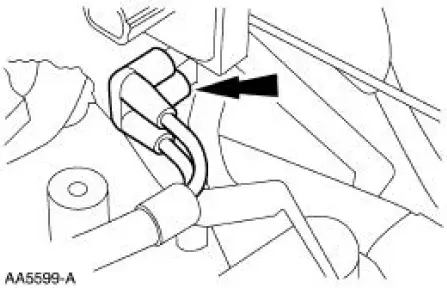
13. Disconnect the EGR vacuum regulator solenoid vacuum supply.
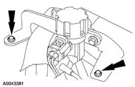
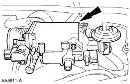
14. Remove the bolts retaining the EGR vacuum regulator solenoid bracket to the intake manifold.
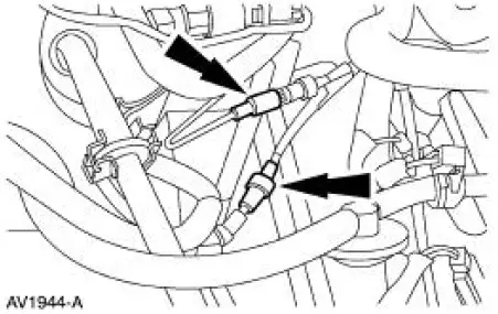
15. Disconnect the exhaust gas recirculation (EGR) tube from the EGR valve.
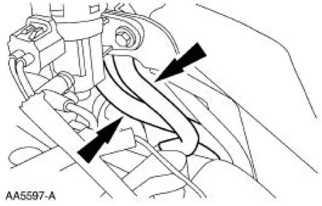
16. Disconnect the positive crankcase ventilation (PCV) hose from the base of the throttle body and spacer assembly.
17. Disconnect the hose from the PCV valve.
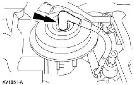
18. Disconnect the vacuum hose from the EGR valve.
19. Disconnect the idle air control (IAC) valve electrical connector.
20. Disconnect the main vacuum supply from the base of the throttle body adapter.
21. Disconnect the throttle position sensor (TPS) electrical connector.
22. Remove the bolts.
23. Remove the throttle body and adapter as an assembly.
- Inspect and clean the sealing surfaces.
- The gasket is reusable if not damaged.
24. Disconnect the fuel pressure sensor electrical connector and the vacuum hose.
25. Disconnect the fuel charging ground wire.
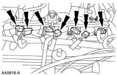
26. Disconnect the ignition coils and the fuel injectors.
27. Disconnect the climate control vacuum supply hoses and remove the vacuum harness.
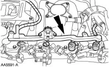
28. Remove the four studs.
29. Remove the injectors and fuel injection supply manifold as an assembly.
30. Remove the ignition coils.
31. Disconnect the battery terminal.
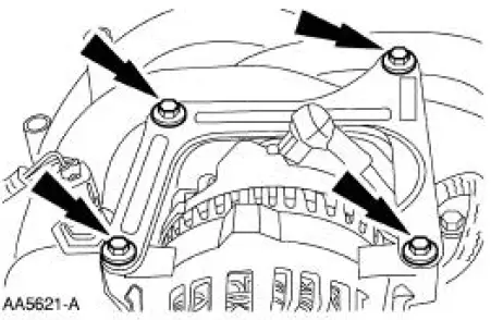
32. Remove the generator support brace.
33. Disconnect the electrical connector.

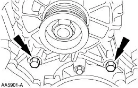
34. Remove the generator.
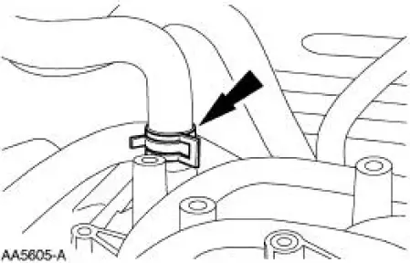
35. Disconnect the heater hose.
36. Separate the engine harness and position it out of the way.
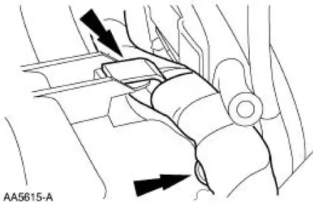
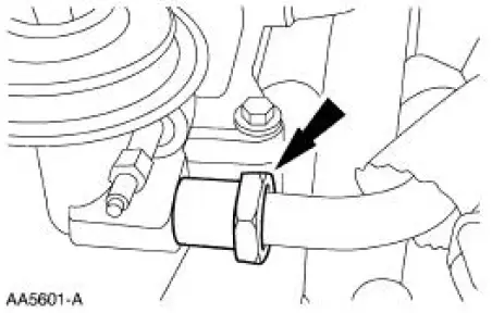
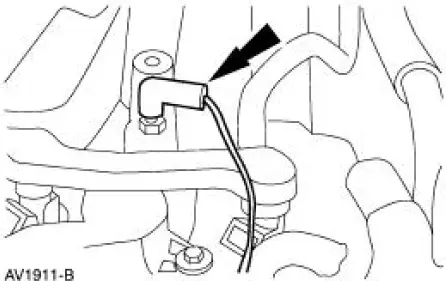
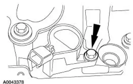
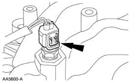
37. Disconnect the water temperature indicator sender.
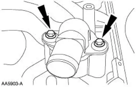
38. Remove the water outlet connector.
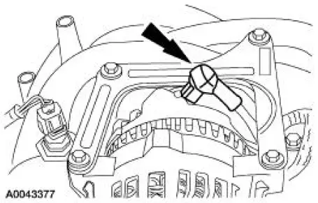
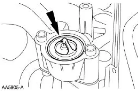
39. Remove the water thermostat and the O-ring.
- Inspect the O-ring and discard if necessary.
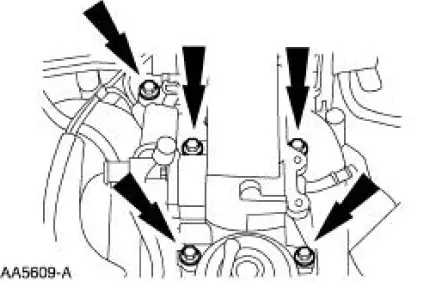
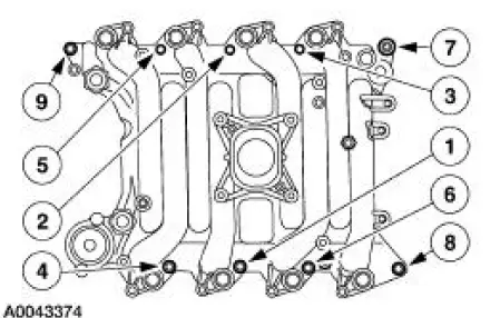
40. NOTE: The gaskets are reusable if not damaged.
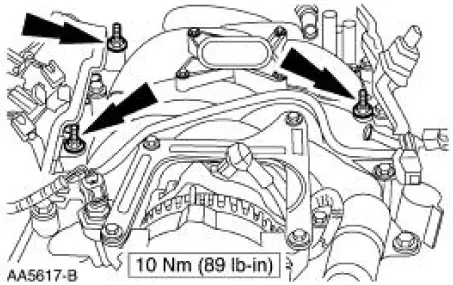
Remove the bolts in the sequence shown, remove the intake manifold and gaskets.
 Intake Manifold
...
 Installation
1. Install the intake manifold and gaskets, tighten the bolts in the sequence
shown.
2. NOTE: The O-ring is to be installed on the top of the thermostat.
Install the water thermostat and the O-rin ...
Other materials:
Removal
Automatic transmission vehicles
1. Remove the flexplate. For additional information, refer to Flexplate in
this section.
Manual transmission vehicles
2. Remove the flywheel. For additional information, refer to Flywheel in this
section.
All vehicles
3. Using ...
Installation
All vehicles
CAUTION: After installing the urethane installed windshield,
the vehicle should not be
driven until the urethane adhesive has cured. The curing time at
temperatures above 13C (55
F) and relative humidity above 50% is 12-24 hours (Refer ...
Door Speaker - Upper
Removal and Installation
1. Remove the front door trim panels (239420). For additional
information, refer to Section
2. Remove the upper speaker access cover.
3. Remove the upper speaker housing.
1. Remove the screw.
2. Remove the upper spea ...
