Ford Mustang (1999-2004) Service Manual: Synchronizers
Disassembly and Assembly
NOTE: This procedure applies to all synchronizer assemblies.
1. NOTE: Synchronizer components are not interchangeable. During disassembly, mark each individual synchronizer for assembly. Synchronizer hubs and sleeves are a selected assembly and should be kept together as originally assembled. Blocking rings are not interchangeable, do not mix.
Scribe an alignment mark on the sliding sleeve and the hub for assembly reference.
2. Using a screwdriver, remove the spring. Turn the synchronizer over and remove the second spring. Remove the sliding sleeve and the synchronizer struts from the hub.
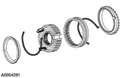
3. CAUTION: Match the alignment marks made during disassembly. The sleeve and the hub have an extremely close fit. Hold the sleeve and hub square to prevent jamming.
Do not force the sleeve onto the hub.
Assemble the synchronizer as follows:
- Position the synchronizer sleeve on the hub. Make sure to align key openings in the hub with the synchronizer sleeve.
- Install the keys with the slots facing the hub.
- Install the spring. Locate the tang to one of the key slots and position into place. Install the second spring. Locate the spring tang on the same key but position in the opposite direction.
 Countershaft
Special Tool(s)
Plate, Bearing Oil Seal
205-090 (T75L-1165-B)
Puller, Bearing
205-D064 (D84L-1123-A)
Installer, Drive Pinion Bearing
Cone
205-004 (T53T-4621- ...
 Gearshift Rail and Fork
Disassembly and Assembly
1. Disassemble the first/second and third/fourth shift rail as follows:
Rotate the interlock plate until it is opposite of the shift links.
Slide off the third/fo ...
Other materials:
Battery and Cables
Vehicles are equipped with a 12 volt maintenance-free battery that
contains a built-in hydrometer. The
hydrometer eye indication is as follows:
A green dot means the battery is OK.
A yellow dot, red dot, or when the green dot is not visible,
...
Trim Panel - Quarter, Coupe
Removal and Installation
1. Remove the upper quarter trim panel. For additional information,
refer to Trim Panel-Upper
Quarter in this section.
2. Remove the scuff plate.
3. Remove the pin-type retainers.
4. Lower the rear seat backrests.
5. Rem ...
Vibrate Software
Vibrate Software (Rotunda tool number 215-00003) is a diagnostic aid which
will assist in pinpointing
the source of unacceptable vibrations. The engine's crankshaft is the point of
reference for vibration
diagnosis. Every rotating component will have an angu ...
