Ford Mustang (1999-2004) Service Manual: Assembly
1. NOTE: Universal joint kits are to be installed as complete assemblies only. Do not mix components from other U-joint kits.
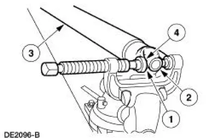
Install the spider.
1. Start a new bearing cup into the driveshaft yoke.
- Check the needle bearings for correct positioning.
2. Position the new spider in the driveshaft yoke.
3. Position the driveshaft in the U-joint tool.
4. Press the bearing cup to just below the snap ring groove.
- Repeat for the other bearing cup.
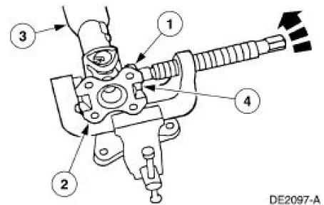
2. Inspect the driveshaft flange yoke. Install new if necessary.
3. Install the driveshaft flange yoke.
1. Start a new bearing cup into the driveshaft flange yoke.
- Check the needle bearings for correct positioning.
2. Position the driveshaft flange yoke.
3. Position the driveshaft in the U-joint tool.
4. Press the bearing cup to just below the snap ring groove.
- Repeat for the other bearing cup.
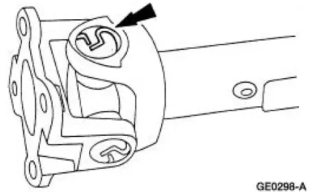
4. NOTE: Use the yellow snap rings supplied in the kit to assemble the universal joint (U-joint). If difficulty is encountered with the yellow snap rings, install the black snap rings, as required.
Remove the driveshaft from the U-joint tool, and install the four snap rings.
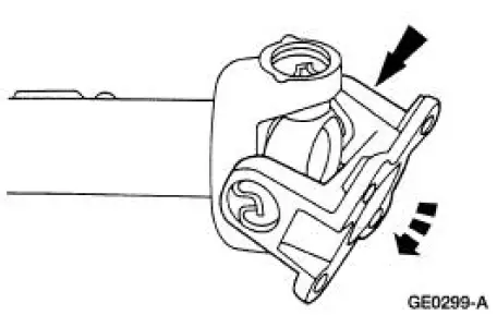
5. NOTE: Do not strike the bearings.
Check the U-joints for freedom of movement.
- If binding, strike the yoke with a brass or plastic hammer.
6. Install the driveshaft. For additional information, refer to Driveshaft in this section.
 Disassembly
1. Remove the driveshaft (4602). For additional information, refer to
Driveshaft in this section.
2. CAUTION: Under no circumstances is the driveshaft assembly to be
clamped in the
jaws of a vise o ...
 Rear Drive Axle/Differential - Ford 7.5-Inch Ring Gear
General Specifications
a: In-vehicle repair refill capacities are determined by filling the rear axle
with the specified lubricant to
6.4-14.3-mm (1/4-9/16-in) below the bottom of the fill hole.
To ...
Other materials:
Wheel Studs
Special Tool(s)
C-Frame and Clamp Assembly
211-023 (T74P-3044-A1)
Removal
CAUTION: Suspension fasteners are critical parts because they affect
performance of vital
components and systems and their failure can result in major service expense. A ...
Towing the vehicle on four whe
Emergency Towing
If your vehicle becomes inoperable (without access to wheel dollies,
car-hauling trailer, or flatbed transport vehicle), it can be flat-towed
(all wheels on the ground, regardless of the powertrain and transmission
configuration) under the fol ...
Keyless Entry/Computer Operated Locks
Programming -Keyless Entry Remote Transmitter
NOTE: All keyless entry remote transmitters (15K601) must be
programmed at the same time.
NOTE: All previous transmitter identification codes (TIC's) will be
erased when programming mode is
entered.
...
