Ford Mustang (1999-2004) Service Manual: Communications Network (Diagnosis and Testing)
Refer to Wiring Diagrams Cell 14 , Multiplex Communication Network for schematic and connector information.
Special Tool(s)
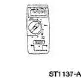 |
73 Digital Multimeter or equivalent 105-R0051 |
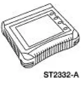 |
Worldwide Diagnostic System (WDS) 418-F224, New Generation STAR (NGS) Tester 418-F052, or equivalent diagnostic tool |
 Module Communications Network
General Specifications
Communications Network
Module Communications Network
...
 Principles of Operation
The vehicle has two module communications networks. The standard
corporate protocol (SCP) which
is an unshielded twisted pair cable (data bus plus, Circuit 914 [TN/OG] and
data bus minus, Circuit ...
Other materials:
Disassembly
1. WARNING: To avoid risk of serious personal injury, follow all
warnings, cautions,
notes and instructions in the driver air bag removal and installation procedure.
Remove the steering column (3C529). For additional information, refer to Column
in this
s ...
Exhaust Manifold - LH
Removal
1. Raise and support the vehicle. For additional information, refer to
Section.
2. Remove the LH exhaust manifold flange nuts.
3. Remove the RH exhaust manifold flange nuts.
4. Lower the vehicle.
5. NOTE: Discard the exhaust manifold gasket.
...
Safety Belt System (Description and Operation)
WARNING: All safety belt assemblies include retractors, buckles, front
seat belt buckle
support assemblies (slide bar, if so equipped), shoulder belt height adjuster
(if equipped), child
safety seat tether bracket assemblies (if equipped) and attaching hardw ...
