Ford Mustang (1999-2004) Service Manual: Pinpoint Tests
CAUTION: Be careful when probing the CJB, battery junction box (BJB) or any connectors. Damage will result to the connector receptacle if the probe or terminal being used is too large.
CAUTION: Electronic modules are sensitive to static electrical charges. If exposed to these charges, damage may result.
NOTE: If DTCs are recorded and the symptom is not present when carrying out the pinpoint tests, an intermittent concern may be the cause. Always check for loose connections and corroded pins.
PINPOINT TEST A: THE MODULE DOES NOT RESPOND TO THE DIAGNOSTIC TOOL - ANTI-LOCK BRAKE CONTROL MODULE
| Test Step | Result / Action to Take |
| A1 CHECK THE VEHICLE FOR TRACTION CONTROL | Yes GO to A2 . No GO to A9 . |
|
|
| A2 CHECK ANTI-LOCK BRAKE CONTROL MODULE C141 FOR DAMAGE | Yes GO to A3 . No GO to A6 . |
|
|
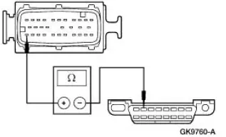
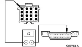
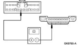
| A3 CHECK FOR OPEN BETWEEN DLC C251 AND ANTILOCK BRAKE CONTROL MODULE C135 - CIRCUIT 914 (TN/OG) | Yes INSTALL a new anti-lock brake control module. REFER to Section. TEST the system for normal operation. No GO to A4 . |
|
|
| A4 CHECK CIRCUIT 914 (TN/OG) BETWEEN DLC C251 AND IN-LINE C144 FOR OPEN | Yes REPAIR Circuit 914 (TN/OG) between anti-lock brake control module C135 and in-line C144. For additional information, REFER to Communication Circuit Wiring Repair . TEST the system for normal operation. No GO to A5 . |
|
|
| A5 CHECK CIRCUIT 914 (TN/OG) BETWEEN DLC C251 AND IN-LINE C215 FOR OPEN | Yes REPAIR Circuit 914 (TN/OG) between in-line C144 and in-line C215. For additional information, REFER to Communication Circuit Wiring Repair . TEST the system for normal operation. No REPAIR Circuit 914 (TN/OG) between DLC C251 and in-line C215. For additional information, REFER to Communication Circuit Wiring Repair . TEST the system for normal operation. |
|
|
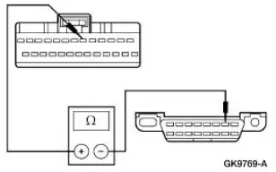
| A6 CHECK FOR OPEN BETWEEN DLC C251 AND ANTILOCK BRAKE CONTROL MODULE C135 - CIRCUIT 915 (PK/LB) | Yes INSTALL a new anti-lock brake control module. REFER to Section. TEST the system for normal operation. No GO to A7 . |
|
|
| A7 CHECK CIRCUIT 915 (PK/LB) BETWEEN DLC C251 AND IN-LINE C144 FOR OPEN | Yes REPAIR Circuit 915 (PK/LB) between anti-lock brake control module C135 and in-line C144. For additional information, REFER to Communication Circuit Wiring Repair . TEST the system for normal operation. No GO to A8 . |
|
|
| A8 CHECK CIRCUIT 915 (PK/LB) BETWEEN DLC C251 AND IN-LINE C215 FOR OPEN | Yes REPAIR Circuit 915 (PK/LB) between in-line C144 and in-line C215. For additional information, REFER to Communication Circuit Wiring Repair . TEST the system for normal operation. No REPAIR Circuit 915 (PK/LB) between DLC C251 and in-line C215. For additional information, REFER to Communication Circuit Wiring Repair . TEST the system for normal operation. |
|
|
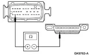
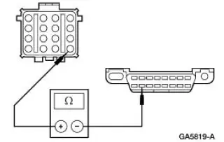
| A9 CHECK FOR OPEN BETWEEN THE DLC C251 AND ANTI-LOCK BRAKE CONTROL MODULE C135 - CIRCUIT 70 (LB/WH) | Yes INSTALL a new anti-lock brake control module. REFER to Section. TEST the system for normal operation. No GO to A10 . |
|
|
| A10 CHECK FOR OPEN BETWEEN THE DLC C251 AND IN-LINE C140 | Yes REPAIR Circuit 70 (LB/WH) between in-line C140 and antilock brake control module C135. TEST the system for normal operation. No GO to A11 . |
|
|
| A11 CHECK FOR OPEN BETWEEN THE DLC C251 AND IN-LINE C314 | Yes REPAIR Circuit 70 (LB/WH) between in-line C314 and in-line C140. TEST the system for normal operation. No REPAIR Circuit 70 (LB/WH) between in-line C314 and DLC C251. TEST the system for normal operation. |
|
PINPOINT TEST B: THE MODULE DOES NOT RESPOND TO THE DIAGNOSTIC TOOL - GENERIC ELECTRONIC MODULE (GEM)
| Test Step | Result / Action to Take |
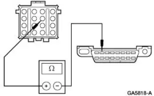
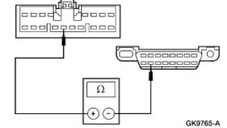
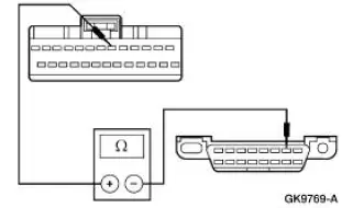
| B1 CHECK FOR OPEN BETWEEN THE DLC C251 AND GEM C201e | Yes INSTALL a new GEM. For additional information, REFER to Section. TEST the system for normal operation. No REPAIR Circuit 70 (LB/WH) between the GEM C201e and DLC C251. TEST the system for normal operation. |
|
PINPOINT TEST C: THE MODULE DOES NOT RESPOND TO THE DIAGNOSTIC TOOL - RESTRAINT CONTROL MODULE (RCM)
| Test Step | Result / Action to Take |
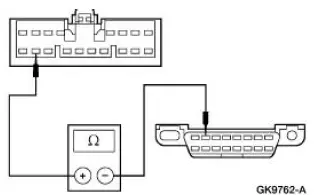
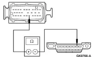
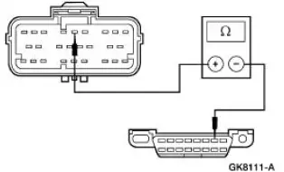
| C1 CHECK CIRCUIT 70 (LB/WH) FOR OPEN | Yes INSTALL a new RCM. REFER to Section. TEST the system for normal operation. No REPAIR Circuit 70 (LB/WH) between RCM C2041 and DLC C251 . TEST the system for normal operation. |
|
PINPOINT TEST D: THE MODULE DOES NOT RESPOND TO THE DIAGNOSTIC TOOL - INSTRUMENT CLUSTER
| Test Step | Result / Action to Take |
| D1 CHECK INSTRUMENT CLUSTER C220a FOR DAMAGE | Yes GO to D2 . No GO to D3 . |
|
|
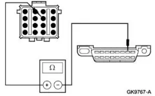
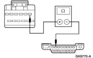
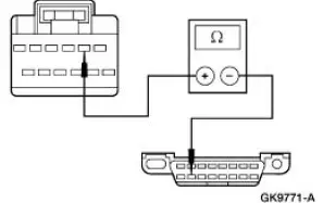
| D2 CHECK FOR OPEN BETWEEN DLC C251 PIN 2 AND INSTRUMENT CLUSTER C220a PIN 1 - CIRCUIT 914 (TN/OG) | Yes INSTALL a new instrument cluster. For additional information, REFER to Section . TEST the system for normal operation. No REPAIR Circuit 914 (TN/OG) between instrument cluster C220a and DLC C251. For additional information, REFER to Communication Circuit Wiring Repair . TEST the system for normal operation. |
|
|
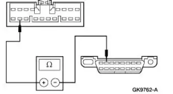
| D3 CHECK FOR OPEN BETWEEN DLC C251 PIN 10 AND INSTRUMENT CLUSTER C220a PIN 2 - CIRCUIT 915 (PK/LB) | Yes INSTALL a new instrument cluster. For additional information, REFER to Section . TEST the system for normal operation. No REPAIR Circuit 915 (PK/LB) between instrument cluster C220a and DLC C251. For additional information, REFER to Communication Circuit Wiring Repair . TEST the system for normal operation. |
|
PINPOINT TEST E: THE MODULE DOES NOT RESPOND TO THE DIAGNOSTIC TOOL - POWERTRAIN CONTROL MODULE (PCM)
| Test Step | Result / Action to Take |
| E1 CHECK PCM C175 FOR DAMAGE | Yes GO to E2 . No GO to E4 . |
|
|
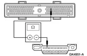
| E2 CHECK FOR OPEN BETWEEN DLC C251 PIN 2 AND PCM C175 PIN 16 - CIRCUIT 914 (TN/OG) | Yes REFER to Powertrain Control/Emissions Diagnosis (PC/ED) manual Section 3. TEST the system for normal operation. No GO to E3 . |
|
|
| E3 CHECK CIRCUIT 914 (TN/OG) BETWEEN DLC C251 AND IN-LINE C215 FOR OPEN | Yes REPAIR Circuit 914 (TN/OG) between PCM C175 and in-line C215. For additional information, REFER to Communication Circuit Wiring Repair . TEST the system for normal operation. No REPAIR Circuit 914 (TN/OG) between DLC C251 and in-line C215. For additional information, REFER to Communication Circuit Wiring Repair . TEST the system for normal operation. |
|
|
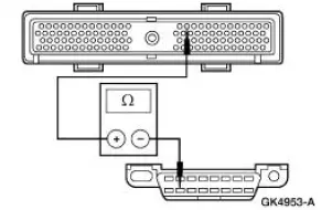
| E4 CHECK FOR OPEN BETWEEN DLC C251 PIN 10 AND PCM C175 PIN 15 - CIRCUIT 915 (PK/LB) | Yes REFER to Powertrain Control/Emissions Diagnosis (PC/ED) manual Section 3. TEST the system for normal operation. No GO to E5 . |
|
|
| E5 CHECK CIRCUIT 915 (PK/LB) BETWEEN DLC C251 AND IN-LINE C215 FOR OPEN | Yes REPAIR Circuit 915 (PK/LB) between PCM C175 and in-line C215. For additional information, REFER to Communication Circuit Wiring Repair . TEST the system for normal operation. No REPAIR Circuit 915 (PK/LB) between DLC C251 and in-line C215. For additional information, REFER to Communication Circuit Wiring Repair . TEST the system for normal operation. |
|
PINPOINT TEST F: NO MODULE/NETWORK COMMUNICATION - ISO 9141 COMMUNICATION NETWORK
| Test Step | Result / Action to Take |
| F1 CHECK CIRCUIT 70 (LB/WH) FOR OPEN | Yes GO to F2 . No REPAIR Circuit 70 (LB/WH) between the GEM C201e and DLC C251. TEST the system for normal operation. |
|
|
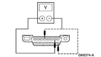
| F2 CHECK FOR SHORT TO GROUND AND POWER AT DLC C251 - GEM C201e DISCONNECTED | Yes CONNECT the GEM module C201e. GO to F3 . No INSTALL a new GEM. For additional information, REFER to Section. TEST the system for normal operation. |
|
|
| F3 CHECK FOR SHORT TO GROUND AND POWER AT DLC C251 - IN-LINE C314 DISCONNECTED | Yes GO to F4 . No GO to F5 . |
|
|
| F4 CHECK FOR SHORT TO GROUND AND POWER AT DLC C251 - RCM C2041 DISCONNECTED | Yes REPAIR Circuit 70 (LB/WH) between DLC C251, GEM C201e, RCM C2041, and inline C314. TEST the system for normal operation. No INSTALL a new RCM. REFER to Section. TEST the system for normal operation |
|
|
| F5 CHECK FOR THE ANTI-LOCK BRAKE CONTROL MODULE | Yes GO to F6 . No GO to F7 . |
|
|
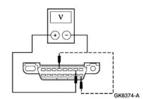
| F6 CHECK FOR SHORT TO GROUND AND POWER AT DLC C251 - ANTI-LOCK BRAKE CONTROL MODULE C135 DISCONNECTED | Yes GO to F7 . No INSTALL a new anti-lock brake control module. For additional information on the anti-lock brake control module without traction control, REFER to Section. For additional information on the anti-lock brake control module with traction control, REFER to Section. TEST the system for normal operation. |
|
|
| F7 CHECK FOR SHORT TO GROUND AND POWER AT DLC C251 - IN-LINE C140 DISCONNECTED | Yes REPAIR Circuit 70 (LB/WH) between in-line C314 and inline C140. TEST the system for normal operation. No REPAIR Circuit 70 (LB/WH) between in-line C140 and the anti-lock brake control module C135. TEST the system for normal operation. |
|
PINPOINT TEST G: NO MODULE/NETWORK COMMUNICATION - SCP NETWORK
| Test Step | Result / Action to Take |
| G1 CHECK DIAGNOSTIC TOOL PINS FOR DAMAGE | Yes GO to G2 . No REPAIR the diagnostic tool terminals. TEST the system for normal operation. |
|
|
| G2 CHECK DLC C251 PINS 2 AND 10 FOR DAMAGE | Yes GO to G3 . No REPAIR the DLC C251. TEST the system for normal operation. |
|
|
| G3 CHECK THE VEHICLE FOR THE ANTI-LOCK BRAKE CONTROL MODULE | Yes GO to G4 . No GO to G7 . |
|
|
| G4 CHECK CIRCUIT 914 (TN/OG) AND CIRCUIT 915 (PK/LB) FOR OPEN - ANTI-LOCK BRAKE CONTROL MODULE C135 DISCONNECTED | Yes GO to G5 . No REPAIR the circuit(s) in question between in-line C215 and DLC C251. For additional information, REFER to Communication Circuit Wiring Repair . TEST the system for normal operation. |
|
|
| G5 CHECK CIRCUIT 914 (TN/OG) AND CIRCUIT 915 (PK/LB) FOR THE SOURCE OF THE CONCERN - ANTILOCK BRAKE CONTROL MODULE C135 DISCONNECTED | Yes GO to G6 . No INSTALL a new anti-lock brake control module. For additional information on the anti-lock brake control module without traction control, REFER to Section. For additional information on the anti-lock brake control module with traction control, REFER to Section. TEST the system for normal operation. |
|
|
| G6 CHECK CIRCUIT 914 (TN/OG) AND CIRCUIT 915 (PK/LB) FOR THE SOURCE OF THE CONCERN - IN-LINE C144 DISCONNECTED | Yes GO to G8 . No REPAIR the circuit(s) in question between in-line C144 and the anti-lock brake control module C135. REFER to Communication Circuit Wiring Repair . TEST the system for normal operation |
|
|
| G7 CHECK CIRCUIT 914 (TN/OG) AND CIRCUIT 915 (PK/LB) FOR OPEN - PCM C175 DISCONNECTED | Yes GO to G8 . No REPAIR the circuit(s) in question between in-line C215 and DLC C251. For additional information, REFER to Communication Circuit Wiring Repair . TEST the system for normal operation. |
|
|
| G8 CHECK CIRCUIT 914 (TN/OG) AND CIRCUIT 915 (PK/LB) FOR THE SOURCE OF THE CONCERN - PCM C175 DISCONNECTED | Yes GO to G9 . No REFER to the Powertrain Control/Emissions Diagnosis (PC/ED) manual Section 3 for diagnosis and testing. |
|
|
| G9 CHECK CIRCUIT 914 (TN/OG) AND CIRCUIT 915 (PK/LB) FOR THE SOURCE OF THE CONCERN - IN-LINE C215 DISCONNECTED | Yes GO to G10 . No REPAIR the circuit(s) in question between in-line C215, in -line C144 (if equipped with the antilock brake control module), and the PCM C175. For additional information, REFER to Communication Circuit Wiring Repair . TEST the system for normal operation. |
|
|
| G10 CHECK CIRCUIT 914 (TN/OG) AND CIRCUIT 915 (PK/LB) FOR THE SOURCE OF THE CONCERN - INSTRUMENT CLUSTER C220a DISCONNECTED | Yes REPAIR the circuit(s) in question between in-line C215, DLC C251, and the instrument cluster C220a. For additional information, REFER to Communication Circuit Wiring Repair . TEST the system for normal operation. No INSTALL a new instrument cluster. For additional information, REFER to Section. TEST the system for normal operation. |
|

PINPOINT TEST H: NO MODULE / NETWORK COMMUNICATION - NO POWER TO THE DIAGNOSTIC TOOL
| Test Step | Result / Action to Take |
| H1 CHECK DIAGNOSTIC TOOL PINS FOR DAMAGE | Yes GO to H2 . No REPAIR diagnostic tool pins. TEST the system for normal operation. |
|
|
| H2 CHECK DLC C251 FOR DAMAGE | Yes GO to H3 . No REPAIR DLC C251. TEST the system for normal operation. |
|
|
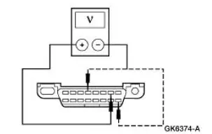
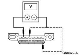
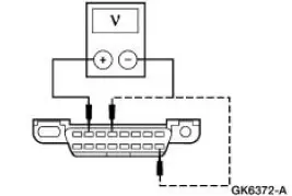
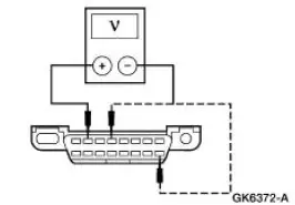
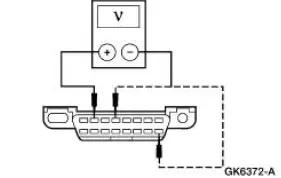
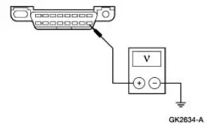
| H3 CHECK VOLTAGE TO DLC C251 PIN 16 - CIRCUIT 1047 (LG/RD) | Yes GO to H4 . No REPAIR Circuit 1047 (LG/RD). TEST the system for normal operation. |
|
|
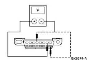
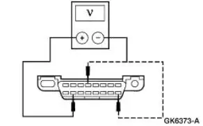
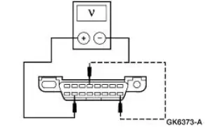
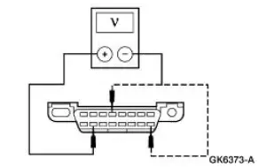
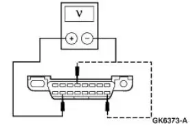
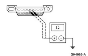
| H4 CHECK THE DLC GROUND - CIRCUIT 1205 (BK) AND CIRCUIT 651 (BK/YE) | Yes CHECK diagnostic tool. TEST the system for normal operation. No REPAIR the circuit in question. TEST the system for normal operation. |
|
 Inspection and Verification
1. Verify the customer concern.
2. Visually inspect for obvious signs of electrical damage.
Visual Inspection Chart
Electrical
Central junction box (CJB) Fuse 31 (5A)
D ...
 Communication Circuit Wiring Repair
Special Tool(s)
Heat Gun
107-R0300 or equivalent
1. Disconnect the battery ground cable. For additional information, refer to
Section.
2. Strip the wires.
3. NOTE: Use rosin core m ...
Other materials:
Condenser Core
Material
Item
Specification
PAG Refrigerant Compressor
Oil (R-134a Systems)
F7AZ-19589-DA (Motorcraft YN-
12-C)
WSH-M1C231-
B
Removal and Installation
NOTE: If an A/C condenser core leak is suspected, the A/C condenser
core must be l ...
Transmission (ASSEMBLY)
Special Tool(s)
Dial Indicator Gauge with
Holding Fixture
100-002 (TOOL-4201-C)
Rubber Tip Air Nozzle
100-D009 (D93L-7000-A)
Alignment Gauge, TR Sensor
307-351 (T97L-70010-A)
Slide Hammer
100-001 (T50T-1 ...
Transmission (Assembly)
Special Tool(s)
Dial Indicator with Bracketry
100-002 (TOOL-4201-C) or
Equivalent
Gauge, Clutch Housing
308-021 (T75L-4201-A)
Extension Housing Seal
Replacer
308-227 (T94P-7657-A)
Holding Fixture
307-0 ...
